

Hydrocarbons
It is an organic compound consisting of two elements, hydrogen and carbon. Most of the petroleum composition consists of hydrocarbons of varying lengths.
The smallest hydrocarbon methane consists of a single carbon atom and four hydrogen atoms. However, hydrocarbons can consist of hundreds or thousands of individual atoms linked together in many ways, including chains, circles, and other complex shapes.
In order to classify the properties of hydrocarbons, they are divided into several basic types.
Alkanes: These are called saturated hydrocarbons. That is, they only contain single bonds between all carbon atoms. Alkanes are the basis of petroleum fuels and exist in linear and branched forms.
Unsaturated Hydrocarbons: Hydrocarbons that have one or more double bonds between carbon atoms are called alkenes.
Cycloalkanes: Any hydrocarbon containing one or more ring structures.
Aromatic Hydrocarbons: Aromatic hydrocarbons , also called arenes, are a unique class of carbon molecules in which carbon atoms are bonded by successive double and single bonds. This class of molecules has special ring structures in which the bonds between carbon atoms are an intermediate bond between single and double bonds.
Molecules in this class contain the industrial solvent "benzene".
Benzene (C6H6): Like other hydrocarbons, benzene is a natural component of petroleum. It is a colorless, flammable, sweet-smelling liquid at room temperature and is a component of most gasoline blends because of its high octane number.
Benzene is also highly carcinogenic and is well known to cause bone marrow failure and bone cancer. Of course, its carcinogenicity is not well known when used as an additive in aftershave and other cosmetics due to its "pleasant aroma".
The largest use of benzene (50%) is the product of styrene and polystyrene plastics. It is also converted into a molecule known as cyclohexane, which is important in Nylon production. About 15% of benzene is used to produce cyclohexane. Smaller amounts are used in everything from pesticides to rubber.
The benzene structure can be drawn in two ways. In the first, the double bond character is drawn explicitly. In the short handed version, a circle is drawn inside the ring to show the structure. There is only one hydrogen bonded to each carbon atom in benzene.
I. and II below. drawings are identical. III in practice. drawing is used.
Benzene is a colorless, flammable liquid with a boiling point of 80.1 ° C and a melting point of 5.5 ° C.
Binuclear Aromatic Hydrocarbons: They are compounds that contain two benzene rings in their molecules.
About
Kyäni, nutritional supplement products consisting of beneficial ingredients; It delivers to more than 50 countries around the world with unique business opportunities. We use Kyäni products daily to maintain our ideal health, share these products with others, devote a certain amount of time to work almost every day to build and maintain our business, and share our success with others by involving others in the Kyäni opportunity or contributing to the Potato Pak and Caring Hands programs.
Page Under Construction.
Page Under Construction.
Training / Knowledge / Solution Platform
THIS PAGE PREPARED OF

Gelişim Valf ve Makina San.Tic.Ltd.Şti.
CONTRIBUTİON
What is Valve?
Mankind's domination of various fluids, especially water and air, these fluids; Mechanical devices used to achieve the purpose of passing or stopping it, adjusting the flow rate, preventing its return, changing the flow direction, limiting the flow pressure and ensuring flow safety are called valves. Valves; It is a mechanical device that gives way to fluids, stops them, mixes them or can change the direction and / or amount, pressure and temperature of the fluid. Fluids that can be controlled for these purposes; It can be liquid, gas, steam, radioactive material, liquid and gas containing solid particles, as well as solid powders such as flour and cement.
History of the Valve:
The Egyptians invented the primitive slide valve in the 5000s BC and the plug valve to bring water to the surface and carry water from underground wells in the 1500s BC.
Farmers were trying to transport water to their land and control it. They noticed that the broken trees diverted the current or even stopped it. As a result, with this method, they expanded the transportation, storage and transportation of water from the water source. Later, they developed their systems a little more and started using them by making wooden or stone obstacles.
Modern valve design began in 1705 to provide the transmission and control of the steam pressure that emerged with the discovery of the first industrial steam engine.
In 1712, the gate valve made of iron was invented, with the invention of the atmospheric machine used to drive low pressure steam into a piston. In the late 1700s, the first double-action machine was invented. This machine made the rise and fall of the piston simultaneously, allowing the steam to reach both sides of the piston. Automatic valves made of iron were used in double-acting machines. Considering today's technological developments, the functions of these valves were very important in terms of the development of steam engines that paved the way for the industrial age and enabled rapid development, although these valves were very simple.
Diversity in Valves:
Valves according to the flow direction; Although it can be straight, corner, three-way, four-way or multi-way according to the body structures; They can be one-piece, two-piece, three-piece or multi-piece.
Valves are also diversified according to their connection equipment; Such as welding connection, screw connection, flange connection, clamp connection, sleeve connection, nipple connection, union connection, clamp connection, brazing connection and compression connection.
In addition, according to the flow control type of valves; They are divided into three main groups as shut-off valves, throttle and control valves and valves that prevent undesired operating conditions.
(Valves that prevent unwanted operating conditions are responsible for preventing unwanted pressure increases and preventing the return of flow in one line or mixing of fluid from one line to the other.)
Valves according to their functions; They can perform one or more of closing, evacuation, pressure adjustment, pressure reduction, flow adjustment, level adjustment, temperature adjustment and mixing tasks. According to the work movement of the closing element; They fulfill their duties by rotating on an axis perpendicular to the linear or flow direction. With today's technology, valves can be controlled with various alternatives. These; mechanical control, hydraulic control, pneumatic control and electrical control.
Decisive criteria in the selection and use of the valve:
For the determination of suitable options for the valves used in industrial facilities, the aforementioned elements provide ease of correct selection.
Some of these main elements are related to the working environment, others are related to the characteristics of the valve itself. It is the lifeblood of the system to take into account all other positive and negative factors as well as circuit characteristics, usage limits of different types of valves, economic life and costs.
1-Functions expected from the valve (Opening, closing, throttling, stopping back flow, adjusting the flow, pressure safety, performing at least one of the stable flow controls)
2- Type of valve
3- Valve size
4- End connection type of the valve
5- Body, cover and trim (in contact with the fluid) material
6- Dimension and design standards
7- Control type
8- The environment where the valve will be used (type of fluid, erosive and corrosive feature)
9- Ambient pressure and temperature
10- Other critical factors
11- Maximum acceptable pressure loss
Connections Applied in Valves
Source link:
In cases where sealing is required (for environmental, safety, hygiene or efficiency reasons), the pipe is welded to the valve and constructed as a single piece. Generally, a permanent connection is required in high pressure applications, especially if high temperatures are present. Nearly all steam and water applications in the power industry are welded. Welding connection is divided into two as welding socket and butt welded.
Screw connection:
Screw connections are generally used in small size valves (DN 40 and smaller). If there is no leakage concern, they can be used up to DN 100. When the valves are used in small sizes, screw connections are very easy to install because the valves are both small and light. It; It makes it easy to connect the pipe with the valve.
Flange connection:
Flanges used in valves are generally used in nominal sizes of DN 65 and above. Flange connections are easier to install than screw connections, because the face of the valve is suitable for fixing the pipe or valve with pipes and bolts without any rotation. Flanges can be used even in high temperatures. However, as the temperature increases, some restrictions occur for high pressures. There are two types of flange designs. These; integrated flange and split flange. Holes in the integral flange are created by machining or casting the valve body. Split flanges are flanges that are subsequently connected to the valve body.
Union connection:
It is an intermediate connection form that enables the assembly and disassembly of the screw-connected valves without causing problematic operations such as removing the pipes.
With compression (sandwich type) connection: It is a type of connection that does not have any connection part, but can be mounted by being squeezed between flanged armatures and / or installation flanges, providing significant reduction in valve size and weight. This type of connection has the advantage of being easy to assemble and disassemble.
Brazing connection:
It is generally used for the connection of valves made of copper and copper alloy to pipes of the same materials. It is an easy connection type. It is not used in high temperature and high pressure applications.
Clamp connection:
Although it is used to connect the hoses to the valve, it is not suitable for high pressures.
Material Properties
ASTM A 216 Gr WCB
Material Group 1.1: It is the carbon steel used in all valves for regular and general use. It is not recommended for temperature conditions above 425C.
ASTM A 216 Gr WC6
Material Group 1.9: 1 1/4 Chrome, 1/2 Molybdenum steel. It is suitable for temperature conditions up to 593C. For weld end valves only. It is up to 538C in flanged ones.
ASTM A 216 Gr WC9
Material Group 1.10: known as 2 1/4 Chrome, 1 Molybdenum steel. It is suitable for temperature conditions up to 593C.
For weld end valves only. It is up to 538C in flanged ones.
ASTM A 217 Gr WC1
Material Group 1.5: Carbon is known as 1/2 Molybdenum steel. Low carbon, resistant up to 455C, suitable for welding, high temperature steel.
ASTM A 217 Gr C5
Material Group 1.13: 5 Chrome, 1/2 Molybdenum steel. It is used under high pressure and temperature conditions. It is suitable for corrosion circuits. Weld joints are a difficult material group. For weld end valves only. It is up to 538C in flanged ones.
ASTM A 351 Gr CF8
Material Group 2.1: Austenitic stainless steel containing 18-21 Chrome, 8-11 Nickel. It is suitable for many corrosive fluid environments. For weld end valves only. It is up to 538C in flanged ones.
ASTM A 351 Gr CF8M
Material Group 2.2: Austenitic stainless steel containing 18-21 Chromium, 8-11 Nickel, 2-3 Molybdenum. It is suitable for situations requiring high corrosion resistance, where 18-8 austenitic stainless steels with high corrosion resistance are generally used. For weld end valves only. It is up to 538C in flanged ones.
You can reach the Pressure and Temperature Tables According to Material Properties here.
Gate Valve / Gate Valve
The gate valve fulfills its duty by opening and closing the fluid passage between the two sealing rings with a sliding bolt that slides perpendicular to the transition direction. Gate valves are divided into two as parallel slide and wedge slide by design.
These valves are used in applications including heavy oil, grease, varnish, molasses, honey, cream and other non-flammable viscous liquids. In addition, hot and cold water installations, steam installations, petrochemical facilities and oil transportation lines can be shown as examples of places of use. Cast iron, cast carbon steel, weapon metal, stainless steel, steel alloys and forged steels are among the material types used in the manufacture of gate valves.
Gate Valves are the basic circuit elements in flow control (on-off process).
It provides a straight transition, the pressure loss is very low. The closing element (slider) moves in a vertical position to the pipe axis, with this movement it cuts the flow and / or gives way to the flow.It provides sealing to metal-to-metal, unidirectional sealing, mainly the bolt and body seats are 3-6 degrees angular (conical surface).
They are operated in fully open, fully closed position. This product group is not used for flow adjustment in semi-open position.
They are controlled with flywheel, gear control, electric and / or pneumatic actuators. The number of on-off cycles depends on the shaft pitch and stroke, and the operation time is long.
It is recommended with flywheel control up to 10 ”Class 150, 8” Class 300, 6 ”Class 600 sizes. After these measurements, the use of gearbox provides convenience in the on-off operation.
Advantages of Gate Valves:
1. Closing properties are very good.
2. These valves can be used bi-directionally in the circuit.
3. They provide straight flow, pressure loss is minimal.
Disadvantages of Gate Valves:
1. Series cannot be turned on or off. For full opening and closing with flywheel or gearbox, the shaft must be rotated by the full number of opening turns. Number of full opening or closing rounds; is up to nominal diameter / pitch.
2. Requires a large area for installation, commissioning and maintenance.
3. The slow movement of the slide in the fully closed position causes a high flow rate. This situation creates abrasion and deformation on the seat surfaces due to vibration and impact, and the friction surfaces are damaged.
4. In systems where high temperature changes irregularly, it causes leakage in the gate valves due to the pipe load at the end of the valve.
5. Repair and maintenance of seat surfaces at the place of use is difficult.
Development API 600 Gate Valve:
Gate Valves (gate valves) are types of general purpose valves that are mainly used in circuits that require full opening and full closing. They provide smooth flow in fully open position. Local pressure loss is very low.
Material Properties:
-
steel casting
-
Alloy Steel Casting
-
Stainless Steel Casting
-
Cast iron
-
Forged Steel (1/2 ”- 2”)
-
Stainless Steel Forged (1/2 ”- 2”
Pressure Classes:
ASME: Class 150, 300, 600, 800, 900, 1500
DIN: PN 10, 16, 25, 40, 63, 100, 160, 250, 350


View Product Catalog >>


Development API 6D Conduit Gate Valve:
Its pressure loss is very low, it provides a smooth transition and a sensitive closing. Seat seating surfaces are parallel, metal and soft seat, sealing rings are double-sided, spring-pressed from the bottom and fully sealed. They can be controlled with gear control, electrical and / or pneumatic actuators. The slider structure is in the form of a flat plate (blade) and a precision grinded structure. It is two-way sealed.
Control and other features are the same as API 600 Gate Valves
Material Properties:
-
steel casting
-
Alloy Steel Casting
-
Stainless Steel Casting
-
Construction Manufacturing
Pressure Classes:
ASME: Class 150, 300, 600
DIN: PN 10, 16, 25, 40, 63, 100


View Product Catalog >>


Ball Valve / Ball Valve
The ball valve is located in the valve group that opens and closes with a quarter turn. They fulfill their duties by cutting and opening the fluid passage by rotating a sphere with one or more holes in the middle, balanced between two gaskets, placed on the end of the shaft, 90o on the fluid transition axis and opening the holes to the passage open or closed position. It is not suitable for precise flow control and it is preferred to operate as on-off when only tight closing is required. Hot and cold water installations, natural gas-oil transportation main lines, gas distribution installations, compressed air installations, petrochemical facilities, machinery manufacturing, special vehicle manufacturing, paper manufacturing, etc. applications are among the places where ball valves are used. Ball valves; They are driven by manual, pneumatic, hydraulic or electric (motor). With actuator control, these valves can be used for on / off or flow control purposes.
If the spherical part has opened the channel and is in the same line with the inlet and outlet ports, the flow from the valve continues uninterrupted. If the valve is full bore, the pressure drop will be minimal. If the valve is narrow pass, the pressure drop will increase. When the valve reaches a quarter turn, the channel blocks flow completely perpendicular to the flow. One-piece, two or three-piece and fully welded types; It is the result of the classification according to the body structure of the ball valve. Another classification is according to the flow direction of the valve, accordingly; They are classified as two-way, three-way and four-way. These valves; It can include materials such as stainless steel and other types of steel, metal alloys, brass, bronze, copper, aluminum, cast iron, ductile iron, ceramic, PVC, PP and PTFE.
Advantages of Globe Valves:
1. Provides leak-proof service.
2. Quickly opens and closes.
3. It is small in size compared to gate valves.
4. It is lighter than gate valves.
5. It has a multi-way design flexibility that is not available in gate and globe valves. Therefore, it reduces the number of valves needed.
6. Provides flexibility in selection with various ball valve designs.
7. High quality ball valves provide safe service under high temperature and high pressure conditions.
8. They are controlled with less force than gate or globe valves.
Disadvantages of Globe Valves:
1. Not suitable for permanent capping.
2. In fluids leaving residue, the particles in the fluid hitting and sticking to the seat surfaces; It causes abrasion, leakage and problems.
Development Floating Type Ball Valve:
Ball valves (ball valves) are in accordance with API 6D standards, with a two-piece body, full bore or shrinking passage. They give a straight transition, the pressure loss is very low. It is a straight transition, fully sealed 90 degree (quarter turn) valve group. The body structure and closing body are in spherical form, and they are one-way impermeable in the opposite direction of the pressure. It opens and closes serially, it can also be used in semi-open position for flow adjustment purposes. They are controlled by lever, gear control, electric and / or pneumatic actuator control. Arm operated is recommended up to 6 ”Class 150, 4” Class 300, 4 ”Class 600 sizes. After these measurements, the use of gearbox provides convenience in the on-off operation.
Material Properties:
-
steel casting
-
Stainless Steel Casting
-
Forged Steel (1/2 ”- 2”)
-
Stainless Steel Forged (1/2 ”- 2”)
Pressure Classes:
ASME: Class 150, 300, 600, 800, 900, 1500
DIN: PN 10, 16, 25, 40, 63, 100, 160, 250, 350


View Product Catalog >>


Development Trunnion Ball Valve:
It is a straight transition, fully sealed 90 degree (quarter turn) valve group. The body structure and closing body are in spherical form, and they are one-way impermeable in the opposite direction of the pressure. It opens and closes serially, it can also be used in semi-open position for flow adjustment purposes. In these types with bottom bearing, the pressing force affecting the sphere in the closing direction under pressure is balanced by these bearings. With the bottom bearing, the soft sites used in both directions are protected against crushing, spreading and other deformations. Soft seat rings have a longer economic life compared to floating types. Arm operated is recommended up to 6 ”Class 150, 4” Class 300, 4 ”Class 600 sizes. After these measurements, the use of gearbox provides convenience in the on-off operation.
Material Properties:
-
steel casting
-
Stainless Steel Casting
-
Forged Steel (1/2 ”- 2”)
-
Stainless Steel Forged (1/2 ”- 2”)
Pressure Classes:
ASME: Class 150, 300, 600, 800, 900, 1500
DIN: PN 10, 16, 25, 40, 63, 100, 160, 250, 350


View Product Catalog >>
Gelişim Two Way Fully Sealed Double Block and Bleed Ball Valve:
The body is 3-piece, bottom and top bearing (trunnion), with the bearing inside the body, all the pressure force affecting the sphere in the closed position is loaded on the body, the sealing rings are free from this force and have a long life.
Straight transition, bidirectional fully sealed, 90 degrees (quarter turn), sealing rings are bidirectional-bottom spring pressed and fully sealed.
In this ball valve group, both-way "leak detection" is possible on the line, and emergency intervention is possible to seat and shaft leaks without removing the valve from the circuit.
They are controlled with lever, gear box, electric and / or pneumatic actuator.
Arm operated is recommended up to 6 ”Class 150, 4” Class 300, 4 ”Class 600 sizes. After these measurements, the use of gearbox provides convenience in the on-off operation.
Material Properties:
-
steel casting
-
Stainless Steel Casting
-
Steel Forging
-
Stainless Steel Forging
Pressure Classes:
ASME: Class 150, 300, 600, 800, 900, 1500
DIN: PN 10, 16, 25, 40, 63, 100, 160, 250, 350


View Product Catalog >>
Pressed Valve / Globe Valve
The pressed valve fulfills its duty by cutting and opening the fluid passage by sitting or lifting the flap connected to the end of the shaft on the fluid passage hole. The flaps are normally in the shape of a plate. Movable shaft is used during the opening and closing of the automatically pressed valves, and this movement of the shaft is controlled by the actuator. If the valve is to be used manually, the shaft is rotated by turning the flywheel on top of it. Although in the past, pressed valves had this name (Globe) due to their spherical body, today's valves are far from spherical. Nevertheless, the term globe valve is used for valves that have a mechanism similar to the internal mechanisms of these valves. Material to be used in pressure valves; It is selected according to pressure, temperature and controlled environment characteristics. Body materials are; copper alloys (brass, bronze), cast iron, ductile iron, steel and stainless steel, and steel and stainless steel, PVC and PP. Especially hot and cold water installations, steam installations, hot oil installations, petrochemical plants, machinery manufacturing, special vehicle manufacturing, etc. they are used in areas.
Advantages of Globe Valves:
1. Full covering properties are good.
2. Dimming properties are good.
3. When compared to gate valves, the stroke and the associated opening-closing time are shorter.
4. Body ring seating surface operation is easier.
5. They can also be used as a stop-check valve with a little precaution to be taken on the shaft and disc connection.
Disadvantages of Globe Valves:
1. Pressure loss is higher compared to gate valves.
2. Requires an actuator with greater force or greater torque to close under high pressure.
Development Globe (Globe) Valve:
These valves are suitable to be used for closing, throttling and adjustment purposes. Globe valves produce high flow resistance due to their working principle. It is a valve type suitable for frequent opening and closing. It is a type of valve that is used for opening-closing, throttling and adjustment purposes and providing sensitive sealing. By drawing a flow (S) inside the body, it changes direction and also makes turbulence. For this reason, the pressure loss is higher than other valves.
Material Properties:
-
steel casting
-
Alloy Steel Casting
-
Stainless Steel Casting
-
Cast iron
-
Forged Steel (1/2 ”- 2”)
-
Stainless Steel Forged (1/2 ”- 2”)
Pressure Classes:
ASME: Class 150, 300, 600, 800, 900, 1500
DIN: PN 10, 16, 25, 40, 63, 100, 160, 250, 350


View Product Catalog >>


Non Return Valve / Check Valve
Check valves are self-operating safety valves and allow flow in only one direction to prevent backflow of gases and liquids. Therefore, they are classified as one-way flow valves. While the flow in the desired direction opens the valve, no flow occurs in the opposite direction. In addition, they do not need any external power supply or signal. Their operation depends solely on the flow direction of the process, which can be achieved with a pump or pressure drop. Most check valves have a ball seated on the seating surface and have only one through hole. The sphere has a slightly larger diameter than the through hole. If the pressure behind the seating surface exceeds the pressure on the ball; Fluid is allowed to flow through the valve. If the pressure on the sphere exceeds the pressure under the seating surface, the sphere returns to its place on the seating surface and rests on the seating surface in a way that prevents flow in the opposite direction.
The most important types of these valves are ball check valve, diaphragm check valve, swing check valve, lift off check valve and double check valve. These valves are used in many different applications, especially in oil, gas, water, treatment, power and chemical applications. Check valves; Although it can be classified according to features such as valve size, pressure classification, ambient temperature and valve flow coefficient; They are made of materials such as stainless steel, steel, brass, bronze, cast iron, ductile iron, aluminum, copper, PTFE, PVC, polyethylene, polypropylene, acetal polymer and rubber.
Advantages of Check Valves:
They open and close by themselves. There is no need for an external intervention for opening and closing. It is fast moving.
Disadvantages of Check Valves:
1. It is difficult to understand whether the valve is open or closed from the outside, as all moving parts are in a closed area.
2. Check valves have various restrictions during the assembly phase.
3. The valve disc may get stuck in the open position.
Development Floating Type (Swing) Check Valve:
These are the valves used to prevent back flow. It works automatically without any remote control. Disc weight provides fast (sudden) closing with the effect of vacuum. When the pump is activated, it opens with the fluid (line) pressure, when the pump is disabled (when the line pressure decreases), the closing element (valve) is automatically closed by its own weight. It does not require any special care. In case of a need for reverse flow at the tank inputs and outputs, it is opened "with the help of an arm to be applied to the shaft from the outside" and provides reverse flow.
Material Properties:
-
steel casting
-
Alloy Steel Casting
-
Stainless Steel Casting
-
Cast iron
-
Forged Steel (1/2 ”- 2”)
-
Stainless Steel Forged (1/2 ”- 2”)
Pressure Classes:
ASME: Class 150, 300, 600, 800, 900, 1500
DIN: PN 10, 16, 25, 40, 63, 100, 160, 250, 350


View Product Catalog >>
Gelişim Spring Loaded (Lift Type) Check Valve:
On vertical lines and / or for some special cases; This type of spring-loaded check valves in the globe valve working principle are more suitable for the "intended use".
It is more preferred than swing type check valve in terms of knocking, vibration and noise on the vertical line.
Material Properties:
-
steel casting
-
Alloy Steel Casting
-
Stainless Steel Casting
-
Cast iron
-
Forged Steel (1/2 ”- 2”)
-
Stainless Steel Forged (1/2 ”- 2”)
Pressure Classes:
ASME: Class 150, 300, 600, 800, 900, 1500
DIN: PN 10, 16, 25, 40, 63, 100, 160, 250, 350


View Product Catalog >>


Gelişim Wafer Type Single Plate Check Valve:
It is a single disc valve connected to the line by compressing between two flanges on the line.
Disc opens automatically with fluid pressure. When the flow pressure drops, the disc fits on the seat surface with its own weight and provides closing. It is generally narrow transitional.
Material Properties:
-
steel casting
-
Alloy Steel Casting
-
Stainless Steel Casting
-
Cast iron
-
Forged Steel (1/2 ”- 2”)
-
Stainless Steel Forged (1/2 ”- 2”)
Pressure Classes:
ASME: Class 150, 300, 600
DIN: PN 10, 16, 25, 40, 63, 100


View Product Catalog >>
Gelişim Wafer Type Double Plate Check Valve:
It is a foldable double disc valve that is connected to the line by clamping it between two flanges on the line.
With the fluid pressure, the butterfly wings-type closing element inside the body is folded over and opened, when the flow pressure decreases, the butterfly-type closing element switches to the normal position with the help of the spring, it fits on the seat surface and provides closing.
It is generally narrow transitional.
Material Properties:
-
steel casting
-
Alloy Steel Casting
-
Stainless Steel Casting
-
Cast iron
-
Forged Steel (1/2 ”- 2”)
-
Stainless Steel Forged (1/2 ”- 2”)
Pressure Classes:
ASME: Class 150, 300, 600
DIN: PN 10, 16, 25, 40, 63, 100


View Product Catalog >>


Development Forged Valves:
Forged valves are compact and used in high pressure circuits. Gate, globe, check and global production can be made.
As a result of the forging process, a better transformation is achieved by tightening the grain structure of the forged material and can be used safely in oil refineries, power plants, gas production facilities and power plants.


View Product Catalog >>


Strainers
They are products used as residue traps in fluid circuits to prevent the sediment fluids from damaging other equipment in the system. Strainers are a piping element used to separate the particles and all other foreign deposits in the fluid by filtering and to send the fluid to the system with the desired sensitivity.
Gelişim Basket Type Strainers:
The fluid filling the basket inside the body from the inlet direction has a “cylindrical internal filter element inserted into the cylindrical internal structure body” and a comfortable filtration volume through which the fluid will divert to the outlet.
The net permeability area of the filter is 150%, 200%, 300% or more different than the pipe section and has the user-preferred sizes and has the desired mesh spacing. It is the most economical strainer in terms of energy consumption because the pressure loss in the pump circuits remains at a minimum level.
Filter Cleaning: The upper cover is disassembled and the inner filter (Basket) is taken out and cleaned.
Material Properties:
-
steel casting
-
Alloy Steel Casting
-
Stainless Steel Casting
-
Cast iron
-
Construction Manufacturing
Pressure classes:
ASME: Class 150, 300, 600
DIN: PN 10, 16, 25, 40, 63, 100


View Product Catalog >>
Development T Type Strainers:
In this filter type Globe body form, the pressure loss is higher as the fluid is directed to the outlet by drawing (S) inside the body. Therefore, it is not preferred for pump outlets.
Filter Cleaning: The dirt can be removed by opening the cleaning plug on the filter cover and / or disassembling the cover.
Material Properties:
-
steel casting
-
Alloy Steel Casting
-
Stainless Steel Casting
-
Cast iron
Pressure classes:
ASME: Class 150, 300, 600
DIN: PN 10, 16, 25, 40, 63, 100


View Product Catalog >>
Development Y Type Strainers:
The fluid undergoes a small angular change of direction within the body, providing the functions described above. Compared to basket filters, the net permeability area is more limited than basket filters due to the geometric form of the body.
Filter Cleaning: The dirt can be removed by opening the cleaning plug on the filter cover and / or disassembling the cover.
Material Properties:
-
steel casting
-
Alloy Steel Casting
-
Stainless Steel Casting
-
Cast iron
-
Forged Steel (1/2 ”- 2”)
-
Stainless Steel Forged (1/2 ”- 2”)
Pressure classes:
ASME: Class 150, 300, 600, 800
DIN: PN 10, 16, 25, 40, 63, 100, 160


View Product Catalog >>


Gelişim Conical Type Strainers:
The filter is a flat or truncated cone-shaped filter in an outer mesh reinforced against crushing and stretching. The filter inlet mouth has a collar suitable for the "nominal size flange" gasket pressing surface, which will be interposed on the line, the conical filter is placed in the pipe and the collar in the inlet mouth is tightened between two flanges to act as a gasket. These types of filters are preferred in some pipe fittings.
Filter Cleaning: Conical filter is taken out of the line together with the piece of pipe in which it is placed and cleaned.
Material Properties:
-
Construction Manufacturing (Steel or Stainless Steel)
Pressure classes:
ASME: Class 150, 300, 600
DIN: PN 10, 16, 25, 40, 63, 100


View Product Catalog >>


Safety Valve / Relief Valve
Safety valves are self-operating valves that are installed in the process to protect the system against exceeding the desired pressure. If the line pressure tries to exceed the limit value, it reduces the excess pressure. Safety valves are placed in process systems where it is thought that excessive pressure may cause explosion problems in pipes and equipment or that abnormal operating conditions may damage the process element. After the pressure in the process line drops to a safe or normal limit, the safety valve is automatically closed. Thus, it allows the system to work normally. Safety valves can be used for gases and liquids, provided that their designs are different.
Safety valves are actuated in one of two general ways.
The first method; It is a direct-acting pressure-relief valve, and the predetermined spring force exerts a force on the opposite side of the closing element, while the process pressure acts on the other side of the closing element. The correct spring rate becomes critical according to the function of the safety relief valve. When the line pressure reaches its maximum limit, the pressure force overcomes the spring force, allowing the spring and disc to retract, allowing the pressure to pass through the sucrose at a predetermined flow rate.
The second method of activation is; It is pilot pressure-relief valve, and a pilot valve mechanism triggers the main valve to open when it observes the system pressure and exceeds the pressure limit. Although some pilot actuation designs place the pilot mechanism inside the valve, most of the mechanism is tied to the outer surface. In addition, the pilot mechanism decides on the operating characteristic of the valve. In pilot safety valves, the closing element is kept in its seat by the fluid used in the process or the external power source or a combination of both.
Safety and relief valves are divided into three groups according to their application areas. The relief valves (relif valves) allow the fluid to be discharged automatically by partially opening when the fluid exceeds the predetermined pressure value in applications where the fluid is being used. This is because fluids are incompressible. These valves allow the fluid to be evacuated by opening the valve proportionally at pressures above the set pressure. In addition, these valves are also called proportional-lift valves. The second group is; They are safety valves, and when the closing element of the valve is slightly lifted from the seat, the valve suddenly comes to a fully open position and the pressure in the line decreases rapidly. Gas and steam are fluids used in applications where safety valves are used. These valves are also called full lift valves.
The third and last group is; They are safety relief valves and provide automatic evacuation when gases, steam or liquids exceed the preset pressure value. It has quick opening characteristics. These valves are also called normal-lift valves. Although the nominal sizes of the safety and relief valves are between 0.25 ”(DN 6) and 20” (DN 500), brass, bronze, cast iron, steel and stainless steel are the main body materials used.
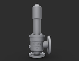
Developmental Safety Valves:
Pressure relief valves are products that automatically release the pressure in closed areas or piping systems at maximum pressure limits. In these products, the maximum pressure limit is based on the product as the set pressure.
In case of change of pressure ranges, the desired adjustment pressure can be restored with the help of the adjustment screw on the product.

Other Valves and Equipments
Piston Valve (piston valve):
The piston valve provides control of the movement of the fluid along the line. They are especially used in applications where high temperature and flow is required and where water or steam is used as fluid. Pneumatic valves are usually operated with compressed pressurized pilot air. Compressed pilot air enters the hole in the actuator cylinder and acts on the piston. The piston also provides the removal of the closing element by means of the shaft. Return of the closing element to its former place; either the return spring in the pneumatic actuator or the valve is made double acting, and the pressurized pilot air is supplied from a second position. Pressure limits; Depends on pilot air, direction of flow, hole diameter, piston diameter of the actuator and valve parameters such as spring force. Piston valves are generally manufactured from materials such as cast iron, ductile iron and steel, but as a connection type to the installation; socket, flange and welding are preferred.
Needle valve :
The shaft of needle valves is thin and has a conical tip and is lowered along the seat to limit and prevent flow. Flow passing through the valve rotates 90o and passes through the orifice. A good threaded connection to the shaft and a wide seat area allow precise resistance to flow. Needle valves are designed for very precise dosing of very small quantities when required. It is very easy to adjust the dosage thanks to its stroke adjustment. It is easy to maintain and practical. It is very easy to use thanks to its small size and mounting screw. These small valves are used to adjust the flow rate of steam, air, gas, oil, water and other non-viscous fluids at low flows in both on-off and throttle services.
Compression Valve (pinch valve):
Compression valves control the flow of media fluid through the hose made of elastic woven fabric. As the name suggests, these valves work with the principle of blocking the opposite walls of the elastic hose so that the ambient fluid cannot pass through. The most important factor limiting these valves is the pressure and temperature values that the elastomer can withstand. Compression valves are generally between DN 50 and DN 300 sizes.
Flow Control Valve :
Flow control valve is used to adjust the flow rate or pressure of a fluid. Control valves normally respond to signals generated by independent sources such as flow meters and thermometers. Control valves are usually found with actuators and positioners. Ball and butterfly valves, especially pneumatically controlled globe valves, also lead the valves used for control purposes in industrial areas. Control valves can also work with hydraulic actuators and these are called automatic control valves. Hydraulic actuators respond by opening or closing the valve according to the change in pressure or flow.
Pressure reducing valve:
The pressure reducing valve (pressure regulator) reduces the pressure of the liquid or gas from the initial value to the last determined value until the process is completed. It is generally used in hot water and space heating systems.
Pilot Valve (pilot valve):
Adjusting the flow rate and pressure of the fluid that will go to the other valves, these valves control higher pressure or flow rate thanks to the small and easy-to-operate and incoming supply. If there were no pilot valves, more force would be required for operation. In addition, they are used in critical applications such as emergency and security control and are operated directly by human beings.
Thermostatic Mixing Valve (thermostatic mixing valve):
This valve achieves constant temperatures by mixing hot water and cold water. Thus, it provides adjustment of the water temperature. In this way, it protects against thermal shock or scalding that may occur as a result of errors that may occur during cold or hot supply.
Explosion Valve (blast valve):
The explosion valve is used to withstand sudden external pressure changes inside the shelter, especially protecting it from situations that result in injury or death. Sudden pressure change may occur as a result of nuclear explosion or similar explosions occurring in a close area. These valves are placed inside the air inlet / outlet pipes in the normally open position. However, in the event of a sudden and strong pressure change, the explosion valve automatically closes itself.
Freeze Valve (freeze valve):
The freeze valve for single phase fluids includes a pipe designed to receive fluid from a cold and hot source through a flow field. Cold welding and hot welding are placed to provide thermal contact with the pipe. In this way, by allowing the fluid passing through the pipe to freeze, it closes the passage in the pipe or allows the passage to be opened by heating the fluid. As a result; The freezing valve prevents or allows the passage by providing both freezing and melting.
Diaphragm Valve (membrane valve):
The diaphragm valve fulfills its task by moving a membrane perpendicular to the flow direction and seating it on the sealing surface. It is a valve that is generally used in hygienic applications and is mainly used as a shut-off valve in process systems including fermentation, genetic research, food and beverage industry, pharmaceutical and biotechnological industries.
Advantages of Diaphragm Valves:
1. It is used for opening - closing and throttling.
2. Good chemical resistance due to the inner coating of the body.
3. The cover group is insulated from the fluid. Therefore, there is no shaft leakage.
4. It provides bubble tightness.
5. There are no pockets in the body that can cause debris and particle build-up. Therefore, it is suitable for heavy fluids.
6. Particularly suitable for hazardous chemicals and radioactive liquids.
7. Since the cover group is insulated from the fluid, it does not allow germs / dirt to contaminate the environment. Thus, it is hygienic for areas such as food industry, pharmaceutical industry, beer industry.
Disadvantages of Diaphragm Valves:
1. If the valve passage is barred, it prevents the pipeline from being emptied completely.
2. Operating temperature and pressure are limited due to the diaphragm material. It is generally used at 200 psi (14 bar) pressure and (204ºC) temperature limits.
3. The hydrostatic pressure that can be applied to the diaphragm is limited.
4. Diaphragm valves are limited in size. It is made in DN15-DN300 sizes.
Butterfly Valve (butterfly valve):
Butterfly valve is in the quarter turn valve group. They fulfill their duties by cutting and opening the fluid passage by rotating a flat disc centrally or eccentrically bedded in the middle of the fluid passage hole by 90o.
Plug Valve (Conical-Cylindrical ):
The plug valve is a quarter-turn valve and it is seated in a conical or cylindrical slot perpendicular to the flow axis and it fulfills its duty by cutting and opening the fluid passage by turning a conical or cylindrical part with a hole in the middle by 90o and turning the hole to the open or closed position. These valves are used in such a way that they can be on-off or throttling. Plug valves were originally designed to replace gate valves and, due to their quarter turn, can open and close faster than a gate valve. The simplest and common type of plug valve is the two-way one, consisting of an open position that allows flow and a closed position that prevents flow. Since these openings are generally at opposite ends of the body, a quarter turn is sufficient to change from open position to closed position. This is the reason why these plug valves are in the quarter turn valve class. It is also possible that these valves have more than two connection ports. With a three-way plug valve, the flow in the first path can be directed to the second or the third. These paths can work in two or two at the same time, or it is possible for three paths to work at the same time. Although they are mostly used at low temperatures and pressures, there are also those used at higher temperatures and higher pressures. They are generally used in chemical, petroleum, petrochemical, gas transportation main lines by-pass and in pharmacochemical applications. Cast iron, ductile iron, steel, stainless steel and bronze casting, glass, PVC, PP and PTFE are among the most used body materials.
Advantages of Plug Valves:
1. It has a simple design with few parts.
2. Easy to open and close. (Except for big sizes)
3. Maintenance repair can be done at the place of use.
4. It shows minimum resistance to flow.
5. Provides reliable sealing.
Disadvantages of Plug Valves:
1. Due to the high friction, it requires great power in the first movement (opening-closing).
2. NPS 4 (DN100) and larger valves require gearboxes or actuators.
3. Depending on the conical plug (plug), the valve passages are of the narrowing type.
4. Generally, their cost is higher than ball valves.
Pressure sustaining valve:
The pressure holding valve (counter pressure regulator) adjusts the pressure to the preset upstream level. It is used during pipe installation. It can essentially match the minimum working pressure in the water pipe, keeping the pressure in the pipeline constant by balancing the upstream pressure with the downstream pressure. If the upstream pressure increases, the passages in the pilot are opened more and lower the pressure.
Gas Pressure Regulating Valve :
Gas pressure regulators are also used to control the gas pressure, to keep it constant and to prevent damage to the downstream installation and to automatically control the flow of gas at a certain pressure. If the pressure of the gas source is higher than the required pressure, it cuts off the flow. In this case, the valve opens and when the pressure drops, it allows flow until the system pressure rises again.
Vacuum Breaker Valve :
The vacuum breaker valve ensures that the vacuum level in the system is controlled by allowing contact with the atmosphere when the vacuum level rises above the set value of the valve. The disk or float inside the valve moves upwards, closing the air vent and allowing the flow of liquid as it passes through the valve. When the flow stops, the disc automatically fits to the surface, thus, while opening the vertical direction to the atmosphere, it prevents the pull in the vertical direction. As a result, this valve is often used to prevent dirty water from being drawn back into the pressurized potable water supply.
Stub Valve (saddle valve):
Stud valve is used when low flow rate and pressure is required, and it is usually mounted directly on the hose. To do this, firstly, the valve should be placed properly on the line, then it should be turned clockwise until it pierces the water line. If the valve is to be opened, the stem of the valve should be turned counterclockwise. There is no need to interrupt the main water supply during the installation of the valve on the line. It is generally used to supply cold water to humidifiers and ice makers in freezers.
Zarp Tap (stopcock):
Zarp faucet is used to limit or prevent the flow of liquid or gas through the pipe. It is generally used in laboratories, steam engines and also to prevent water from flowing into local water systems when events such as flooding are encountered.
Comb Valve (reed valve):
The comb valve is a simple one-way valve, but consists of two or more flexible materials pressed together in lengths.
Faucet (tap):
Faucet is a simple valve that is used in homes and allows the adjustment of the water flow. It controls the discharge of liquid or gas. Examples are sinks, bathtubs, laboratory and beer taps.
Screw Faucet (bibcock):
The screw tap is used to connect the hose to the water supply outside the buildings. Especially car washing and garden irrigation are the most frequently used applications of such valves.
Float Valve (fill valve / ballcock):
The float valve is used to control the water level and prevent overflow during filling the water tanks. Usually found in toilet flushes. The valve, which is the most important element of the mechanism, is attached to the float and is located near the top of the tank. The valve is connected to the source where the water comes from and is opened and closed with the help of a lever. If the water level has reached the filling level, the float forces the valve to close. This causes the valve to stop the flow of water. When the water level in the tank decreases, the float lowers and activates the float valve and the water starts to fill the tank again. This filling continues until a certain level is reached.

About us:
Gelişim, established in 1989 in Istanbul, has superior knowledge and experience in the production and sales of industrial valves. It is at the service of our sector with modern processing benches and test equipment in its factory located in Tuzla, Istanbul, and continues its production successfully in API, ASME, DIN, TSE standards. Its production capacity has reached 1500 tons / year.
Our valves:
-
Turkey, Middle East and many countries can stream forming the vessels industrial control circuits included in the Commonwealth of Independent States,
-
Refinery, filling and all other oil facilities,
-
In the chemical industry,
-
It works with high performance in all other important industrial facilities, especially in energy and iron and steel.
Certification:
-
Our products are TSE 13942 / 21.06.2007 certified.
-
CE marking has been audited by the approved organization Türk Loydu.
-
GELİŞİM's success in its field of activity has certified its ISO 9001: 2015 quality assurance system from Türk Loydu.
-
Gate Valves, Globe Valves, Check Valves have been tested by TÜV Austria and certified with a fire safety certificate within the scope of API 6FA, API 607 and ISO 10497-5: 2004 standards.
-
Our Gate Valves API 600, API 6D, Check valves API 6D, Ball valves API 6D and API 608 monogram.
It shares the rightful pride of being the best and maintaining its success today and in the future as it was in the past with its customers. It will continue to stay different with excitement with original design studies based on customer satisfaction.
Gelişim has carried out its quality policy "based on data and information, in compliance with customer requirements, in a healthy cooperation with its suppliers, with the participation of employees and continuous improvement efforts" with sensitivity to "society and the environment".
Quality Certificates:
Our products have been TSE 13942 certified since 21.06.2007. CE marking has been audited by the approved organization Türk Loydu. Its success in its field of activity has certified its ISO 9001: 2015 quality assurance system from Türk Loydu.
Gate Valves, Globe Valves, Check Valves have been tested by TÜV Austria and certified with a fire safety certificate within the scope of API 6FA, API 607 and ISO 10497-5: 2004 standards.


In Preparing This Page
For his contribution
Gelişim Valf ve Makina San.Tic.Ltd.Şti.
We thank you.