

Hydrocarbons
It is an organic compound consisting of two elements, hydrogen and carbon. Most of the petroleum composition consists of hydrocarbons of varying lengths.
The smallest hydrocarbon methane consists of a single carbon atom and four hydrogen atoms. However, hydrocarbons can consist of hundreds or thousands of individual atoms linked together in many ways, including chains, circles, and other complex shapes.
In order to classify the properties of hydrocarbons, they are divided into several basic types.
Alkanes: These are called saturated hydrocarbons. That is, they only contain single bonds between all carbon atoms. Alkanes are the basis of petroleum fuels and exist in linear and branched forms.
Unsaturated Hydrocarbons: Hydrocarbons that have one or more double bonds between carbon atoms are called alkenes.
Cycloalkanes: Any hydrocarbon containing one or more ring structures.
Aromatic Hydrocarbons: Aromatic hydrocarbons , also called arenes, are a unique class of carbon molecules in which carbon atoms are bonded by successive double and single bonds. This class of molecules has special ring structures in which the bonds between carbon atoms are an intermediate bond between single and double bonds.
Molecules in this class contain the industrial solvent "benzene".
Benzene (C6H6): Like other hydrocarbons, benzene is a natural component of petroleum. It is a colorless, flammable, sweet-smelling liquid at room temperature and is a component of most gasoline blends because of its high octane number.
Benzene is also highly carcinogenic and is well known to cause bone marrow failure and bone cancer. Of course, its carcinogenicity is not well known when used as an additive in aftershave and other cosmetics due to its "pleasant aroma".
The largest use of benzene (50%) is the product of styrene and polystyrene plastics. It is also converted into a molecule known as cyclohexane, which is important in Nylon production. About 15% of benzene is used to produce cyclohexane. Smaller amounts are used in everything from pesticides to rubber.
The benzene structure can be drawn in two ways. In the first, the double bond character is drawn explicitly. In the short handed version, a circle is drawn inside the ring to show the structure. There is only one hydrogen bonded to each carbon atom in benzene.
I. and II below. drawings are identical. III in practice. drawing is used.
Benzene is a colorless, flammable liquid with a boiling point of 80.1 ° C and a melting point of 5.5 ° C.
Binuclear Aromatic Hydrocarbons: They are compounds that contain two benzene rings in their molecules.
About
Kyäni, nutritional supplement products consisting of beneficial ingredients; It delivers to more than 50 countries around the world with unique business opportunities. We use Kyäni products daily to maintain our ideal health, share these products with others, devote a certain amount of time to work almost every day to build and maintain our business, and share our success with others by involving others in the Kyäni opportunity or contributing to the Potato Pak and Caring Hands programs.
Page Under Construction.
Page Under Construction.
Training / Knowledge / Solution Platform
Injection Molding

SCREW / SLEEVE
MAIN ENGINE
HEATER / RESISTANCES
POLYMER (MELTED)
MOLD COOLING LINES
MOVING PLATE
FIXED PLATES
LOCKING MOTOR
FEEDING / DOSING
RAM SCREW MOTOR
POLYMER (GRANUL)
LOCKING UNIT
PATTERN
INJECTION UNIT
It is a processing technique in which the molten polymer is forced into a mold cavity under high pressure through an open channel (runner) and the polymeric melt is allowed to take the form of a mold. Injection molding machine and extruders are very similar. The main difference between the two machines is the screwing process. There is continuous forward pressure in the extruder screw. The screw of the injection molding machine not only moves forward pressure, but also backward movement according to the steps of the molding cycle. Because of this reciprocating motion it is referred to as a "reciprocating screw". Holding Pressure: By injecting the molten polymeric material into the mold and then pulling it back in a few seconds molding process (this process varies according to mold size, raw material type), the polymeric material tends to flow backward through the mold. In order to prevent flowing out of the mold, that is, to confine the melt into the mold, pressure is continued for a while. This holding pressure is also called "ironing pressure", which is wrong. The polymeric material is kept in the cooled mold until it solidifies, after the cycle period is completed, the molds are opened and the finished product / semi-finished product in mold form is obtained. Commonly used thermoplastics in Injection Molding are PP, PC, ABS, N6. Injection Molding is mainly used for Thermoplastics, but Elastomers and Thermosets can also be extruded.
By Injection Molding; A wide variety of products can be created, such as pipe fittings, battery housings, toothbrush bases, bottle caps, disposable razors, forks, spoons, plates, automobile bumpers and dashboards, electrical appliance housing, television cabinets, electrical switches, toys. Thermoset plastics can also be processed with some modifications. The plastic material is injected into a mold with high pressure; the pattern is the negative (reverse) of the desired shape.


Screw Injection Molding: The most used type is screw injection machines. It consists of four basic units: on-off unit, mold, injection unit and control unit. Granular plastic raw material is put into the funnel-shaped tank. Plastic granules descending on the screw shaft from the lower part of the funnel are dragged towards the injection nozzle by the rotation of the spiral screw shaft. Apart from the screw shaft cylinder, the heaters located all around bring the dragged plastic raw material to the desired temperature. Temperature melts the plastic material, making it fluid like honey. The honey-like plastic raw material is injected into the cavity in the closed mold by passing through the injection nozzle. The part is cooled out of the mold.
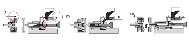
Reciprocating Injection Molding: Reciprocating injection machines are used to mold small capacity and simple parts. Reciprocating machines are not used much today, except for the production of very small parts weighing a few grams, due to the fact that the material is not heated homogeneously. If a reciprocating machine is used, there is approximately 10 dosage of material in the cylinder and this material is heated and melted.
Working principle,
(1) the mold is closed and brought closer to the nozzle (at the same time the molten material is compacted),
(2) injection of material into the mold (simultaneously for the next filling
special feeding adjustment is made),
In (3), the piston is retracted, dosing granules are taken into the cylinder, the runner is
it can be summarized as tearing off, opening the mold and pushing the part out of the mold.
Basic Variables in Injection Molding
Topics to be considered on basic variables are under four main headings as Temperature, Pressure, Cycle Times and Speed.
Temperature:
It is collected under two subtitles as material temperature and mold temperature.
The temperature of the material should be suitable and uniform for the type of material. The temperature of the material at the nipple must be known. The material temperature should be in the middle of the temperature range given by the mix suppliers. The best way to find out the melt temperature is to measure it directly. There are two methods to make this measurement.
1- Core temperatures with immersion / rod pyrometer
2- The surface temperature is measured with the infra red pyrometer. The basic principle in injection depends on the principle of sending the hot plastic into the mold and taking the shape of the mold cavity, thus cooling and hardening the mold. Mold temperature is important as it affects the printing time and part quality. Although plastic flows very easily in a hot mold, the time the print is cooled down and ejected will be longer. On the other hand, the cooling of the molten plastic in the cold mold is quick, but as the fluidity in the mold cavity decreases, it cools and hardens before filling the mold completely.
To find the best conditions between these two situations; It is necessary to pay attention to the type and type of plastic to be used, the flowing length of the plastic, the wall thickness of the plastic part, the type of runner and runner length to be used, and the quality of the desired part. During the mold filling, the hottest molten plastic is at the entrance to the mold and the furthest point from the coldest plastic runner entrance. If the temperature of the mold cannot be adjusted well, this temperature difference causes the formation of undesirable tensions, weak points, material joints in the plastic part. In order to prevent these, it is necessary to provide an even temperature distribution in the printing. This can be achieved with the most suitable cooling systems to be designed in the mold. This is possible by providing cold water in the hot parts of the mold and hot water in the cold parts.
Slow flowing water is considered to have a laminar flow. However, turbulent flow should be preferred in mold cooling cycle and cooling.
Re <10000 laminar flow
Re> 10000 is expressed as turbulent flows.
Mold temperature is ideally the temperature given by plastic manufacturers, such as injection material temperature.
Laminar Flow:
Very regular flow motion indicated by smooth stream lines is called laminar flow. The movement of highly viscous fluids such as oil at low speeds is generally laminar. Highly irregular fluid motion usually occurs at high velocities and is indicated by variations in flow called turbulent.

Pressure:
The plastic material is injected into the mold cavity at a certain pressure. With this pressure, it is ensured that the plastic material takes the shape of the mold cavity. When the pressure is removed, the plastic is still fluid and wants to return to its previous geometry. Due to the plastic's ability to stretch and stretch very easily, we must apply excessive pressure to the mold cavity so that when the material temperature drops and the part cools, no gaps form at the press outlet. When the mold is filled with plastic, it will be necessary to expel the trapped air in this time. When the mold is opened, there are two points to be considered:
1- To prevent the part from sticking to the fixed side of the mold (injection side)
2- Separating the part pushed by the ejector system
Some molders argue that the molds cannot adapt to the machines. In other words, when the same mold and plastic conditions are met, it is said that the same performance cannot be obtained when connected to different machines. In a sense, this is absurd. The material cannot read the ID of the machine on which it is being processed. So if the conditions are the same, it should ultimately be the same. However, there are some differences. The first mistake made at the hydraulic press head is thought to be an error by the operator who reads the pressure, due to the pressure on the plastic. Hydraulic press work works on a principle called force doubler. In the plastic business this is in a ratio of 8: 1 and 12: 1. However, there are many exceptions. It is very clear that if a press is operating at a ratio of 8: 1, a pressure of 1000 kg of plastic is equivalent to a pressure of 8000 kg. The ratio of 12: 1 used in the same machine will create a pressure of 12000 kg. This difference in pressure will cause the machine to signal an error. According to these pressure ratios, each machine should be classified according to its own force doubler and the machine should be adjusted according to these data by making a table accordingly.
Many machines are computer controlled and the data processor
It is reading within the range.
However, machine manufacturers use valve systems that can be activated in only 10ths of a second.
This difference in sensitivity of course causes the machine to slow down and cause problems. The valves of this type of machine should also be selected accordingly. Thus, progress will be made in control. According to the finger rule, if the pressure is applied the same on the material, the same dimensions are obtained in the mold and consequently the same dimensions on the part.
Injection Pressure:
Pressure applied into the mold by the extruder to fill the mold chamber.
Holding Pressure: It is applied to meet the shrinkage of the plastic material and to take its full shape. After the plastic material is injected into the mold and the mold is fully filled, in the second phase, it tries to escape from the entry point in the mold, in order to prevent this movement, the holding pressure is applied after the injection pressure. In other words, the plastic material is kept so that it does not escape.
Back Pressure:
It is defined as the resistance to screw backward movement and helps the material to be heated by friction. It is the pressure created by the screw on the plastic during the material receiving phase while going backwards. This pressure ensures that the mixture is at the optimum level if dye is used. In the case of giving excessive pressure, it disrupts the structure of the material due to the heat of friction.
Cycle Time:
The interval in which a cycle is completed from the beginning to the end is called the cycle time / time. When the material is in the molten state, it is desired to fill the mold very well.
When the material starts to cool, it becomes solid enough and the injection machine starts to be prepared for the next part. It does not matter if the material is simply cooled. What matters is how it cools down. If we want to express what is meant to be explained here, "Before the plastic becomes solid, it needs a little nap." In other words, it is not an optimal situation in terms of plastic to cool immediately. For low cycle times, minimum times should be used.
Filling time:
It is just the time it takes to fill the mold chamber.
Holding time:
In order to reduce shrinkage, the part is kept in the mold under holding pressure. As the piece is pulled, new melt is filled inside. The holding phase continues until the gating entrance freezes. By always working at the same holding times, parts of the same weight can be obtained.
Ironing time: It is only the time required to compress the material in the mold chamber.
Cooling Time:
It is the time until the part has sufficient rigidity and coldness inside the mold.
Mold Open Time:
It should be minimal and not change. The mold open time consists of the opening of the mold, the removal of the part by the impact of the pushers and the closing time of the mold.
Speed:
The speed of filling the mold chamber is called the injection speed. The high injection speed ensures that the cavity is filled with low viscosity and well-melted material. With small runner entries, high injection speed, mechanical and cosmetic errors may occur in the part.
Temperature, pressure, cycle time, and speed are all changes during use of these four variables.
it often appears that speed is primarily variable. Filling speed is directly dependent on melt viscosity. This depends on the desired filling pressure. Small changes in speed dramatically affect the machine's ability to fill the mold cavity.
The viscosity of the material depends on this speed; it is probably the most critical variable and its modification has the least impact on others. Pressure is the second variable that should be used. It can be adapted in a very short time period with little effect on the overall process. The change in cycle time is immediately reflected in the melting temperature of the material. Changes in temperature easily change the viscosity. This affects the pressure and speed. The temperature is the most difficult variable to adjust. Because it is easy to give heat to plastic, but it is also very difficult to extract heat from it.
Injection molding, one of the plastic processing techniques, has 7 basic cycles.
(1) Plasticization: The work of melting plastic raw material, making it ready to be injected into the mold. First, granular raw material is taken into the furnace, the raw material is melted by heaters and screw friction, the melted plastic is delivered to the screw hole in the front.
(2) Closing the Mold: With the clamping unit of the machine, the two parts of the mold are closed on top of each other and high pressure is applied. The mold space between the two mold plates (male mold and female mold) is formed and the opening and loosening of the mold is prevented against the high pressure and speed applied.
( 3) Filling the Mold: First the screw is pushed forward by the hydraulic piston. The melt is filled into the plastic mold cavity.
(4) Pressure Application: Pressure is increased. Filling of the mold is provided to create fine details.
(5) Holding: The part is held under pressure in the mold to reduce shrinkage. As the piece is pulled, new melt is filled inside. The holding phase continues until the gating entrance freezes.
(6) Cooling: After the runner is frozen, the part cools and shrinks in the mold. The process is continued until the part cools down and reaches its softening temperature.
(7) Unmoulding: The part is removed from the mold with the help of the ejector system.
As can be seen, six of the seven basic cycles, excluding plasticization, take place on the mold unit.
Some of Injection Parameters

Mold Elements in Injection Molding
The injection mold consists of many units that can be complex to withstand the injection pressure.
First of all, molds consist of two units as «female» and «male». Various elements are available on both units:
Female Core:
It is the brightest steel of the mold where the part geometry is processed and where the gating entrance is usually found.
Male Core:
Steel in which the part geometry is processed, forming the mold cavity with the female mold, pushers and other moving elements work.
Female Bearer:
Main bearing steel around the female core.
Male Bearer:
Main bearing steel around the male core.
Centering Flange:
Centers the mold on the injection machine plate.
Centering Shafts:
These are the spindles that center the female and male plates of the mold.
Runner Bushing:
It carries the molten material from the screw of the injection machine to the mold separation line.
Female Connection Plate:
It allows the mold to be connected to the injection machine.
Insulation Plate:
It helps the heat balance of the mold by reducing heat losses and provides cost savings.
Cooling Channels:
Waterways located in the bearer and preferably in the core.
Support Plate:
Supporting unit for male bearer plate to withstand high pressures.
Ejector Support Plate:
Plates to which the pushers that remove the part are attached and that provide the pushing movement with the forward movement of the pins.
Parallels:
It provides enough space for the movement of the ejector plate.
Support Column:
It prevents the support plate from bending and provides resistance against the applied pressures.
Thrust Bearing Shafts:
It prevents the pusher plate from damaging the mold / part by oscillating in the axial direction.
Thrust Bearing Shaft Bushing:
They ensure that the pushers move only in the desired axis.
Retractor:
Returns the pusher plate as the mold closes.
O-Ring:
It prevents leakage of coolant from the cooling channels.
Amazing:
It is used to direct the liquid circulating in the cooling channels.
Plug:
Parts defined to plug the ends of certain channels to form a water circuit.
Closing Locking Systems in Injection Molding
The fact that the injection process is not a continuous process requires the mold to be opened to remove the product and to be closed again for the next press. Closing / Locking systems (Clamping unit) perform this process. Since the plastic is injected into the mold at very high pressures, the clamping unit must keep the mold tightly closed (locked) during the injection and holding pressures, preventing the mold from opening and making burrs. The task of this unit is to close and open the mold, keep the mold closed at high pressure and prevent burr formation on the mold separation line. It can be in three types as hydraulic, hydromechanical and mechanical closing locking system.
(1) Hydraulic closing / locking
The system works with the application of hydraulic force.
The hydraulic piston is on the moving side of the machine. The forward movement of the plate and the force applied are controlled by the load pressure applied to the fluid in the closing cylinder. The speed of movement of the plate is usually controlled by the ratio of the liquid's inlet and outlet velocities. Hydraulic clamps are used in high tonnage injection molding machines.
Typically it is between 1,300 and 8,900 kilonewtons (150 and 1,000 tons). Units are more flexible than buckle clamps in terms of adjusting tonnage at certain positions during stroke.
(2) Hydromechanical closing / locking
The hydraulic actuator controls the movement of the cylinder butterfly system and links, thereby enabling the moving plate to open and close. The locking force is provided mechanically by opening the throttle system. Mechanical advantage is obtained due to the connections in the design. This happens by multiplying 1/20 of the hydraulically applied force. The locking force can be adjusted by adjusting the locking height. This is achieved by turning the connections in the locking screw back and forth. The locking tonnage is calculated from the elongation in the columns. Designed for large tonnages over 8,900 kilonewtons (1,000 tons), hydromechanical clamps use hydraulic cylinders to quickly move the mold towards the closing position. Mechanical interlocks provide continuity of the closed position.
(3) Mechanical closing / locking
They are generally best suited for low tonnage machines. It has a working principle on hydraulic cylinders or ball screws driven by electric motors. Toggle clamps supplying mechanical pressure can be of a wide variety of designs. Basically, there are moving equipments that move the head forward, with articulated connection and work with scissors technique. And all equipment is connected to the main actuator. With mechanical joint clamps, it allows the speed and force (pressure) to be changed at different points in the cycle if needed.
Mold Systems in Injection Molding
Screw Mechanism Molds:
A special mold design is required for parts with helical grooves on the cylindrical inner and outer surfaces. The screw can be protruding on the part, making the design even more complicated.
These mixes;
(1) Screw with external thread, internal thread, intermittent or continuous,
(2) Screw formation by printing or using metal parts inserted into the part,
(3) The desired gear form may be in the form of allowing or not allowing the printing to peel off from the mold. In this type of mold, rotation of the male or female mold is considered in order for the part to exit the mold. In order to provide this rotational movement, a system that will provide rotational movement is placed on the moving side of the mold.
Various mechanisms can be used to achieve this.
(1) Axial direction fixed design, little rotation to remove the screwed male part.
(2) Pusher plate design; As the pusher moves, the screw male rotates.
(3) The male design, which is pulled by rotating, works by pulling the male towards the male plate in addition to the rotational movement and the piece remains idle.
(4) Rotating gear plate design, Various hydraulic-pneumatic, electrical power sources are used to operate this kind of molds.
Gear system, chain and sprocket, toothed rod and small gear, rack and pinion are used as power systems. When the rotating male screw attached in the axis direction is rotated, the part is ejected. The mold cavity remains constant. The outer surface of the print should be such that the part should not rotate with the man while the man is turning. Cylindrical parts with flat outer surfaces are not suitable for this system. Because the mold connection of the print is cooled and pulled, the part has a tendency to rotate in the mold cavity. The length of the threaded portion of the male should ideally be slightly less than the mold cavity. If the threaded section is too short in relation to the depth of the mold cavity, the ejector pin attached to the center of the screw will be required to allow the part to be ejected from the mold after screw removal is complete.
Two Plate Molds:
It is the most widely used injection mold in the mold industry. Briefly, it consists of male and female molds. The surface where these two mold parts meet is called the mold separation line. They are preferred because they are the cheapest and easily designed molds that provide convenience to the user. The mold cavities are mounted on one plate and the other plate is closed on this plate. A central vertical runner is machined into a fixed plate. The moving part provides the required closing force and operates the propulsion systems.

Three Plate Molds:
In this type designed for multi-cavity molds, there is also one more movable plate. The mold consists of three separate plates and when the mold is opened, these three plates are separated from each other. One opening provides space for the part to be ejected, while the other opening provides space for the entry runner to be ejected. It takes more time to make and is more costly than a two-plate mold. Central or axial offset gates can be used in this type of design. Runnerless or hot runner mold technology has reduced the tendency to use a three-plate mold. It has some advantages compared to hot runner molds.
(1) It allows the material and color to be changed easily while using the mold. It provides fast color change without long-term contamination of the material by cleaning the runner system in every print.
(2) Reliability; It causes deterioration in temperature control in hot runner systems, heating the system, power outages and failures. Three plate molds are operated with more mechanical parts.
(3) Cost; Mold heaters and temperature control devices (thermocouple, resistance) are very expensive.

Core Molds:
It is also known as angle moving dies. The undercuts that prevent the part from being ejected from the mold are formed on the part, and the core system is used in the molds to ensure that the part comes out without facing any force in the opening direction of the mold. In such designs, the movement of the parts in the male mold that cannot be moved by the press is aimed. With the use of camshafts or angle pins, a secondary movement of the mold elements is achieved. This secondary movement is performed with the help of pneumatic or hydraulic cylinders.

Folded Molds:
These are the molds that enable the molds, which will have a very large mold size when made with two chambers, to work in lower tonnage machines. It can be applied for parts with high production quantities. These quantities can be achieved by making two separate molds, but the cost of the part will increase and the machine capacity will be negatively affected by separating two separate injection machines.
will affect. The groove extends to the second chamber and fills the first chamber after the second chamber is filled, when the mold plates are separated, the middle plate (female plate) is separated from the two male plates, and the first part is separated from the mold with the help of the mechanical pusher plate in the second male mold, and the second part is separated from the mold with the help of hydraulic pushers in the first male mold. . It is more economical compared to mold cost. Considering the cost of the part, it is lower than the cost of the part obtained from two separate molds. Because two parts will be obtained from a single mold in one cycle time and the machine, which affects the cost of the part, is more economical when considering the hourly rate, labor and cycle time.

Reverse Patterns:
In some applications, the fixed side of the injection machine can have male molds and pushers, and a female mold on the moving side can have a built-in design. In this design, pushers are operated mechanically with the help of hydraulic, pneumatic systems or springs. These applications are due to part designs. It is a molding system that can generally be applied to cosmetic product parts. When no traces are desired on the visible surface of the part (runner track, pusher track, running core tracks, etc.), it may be desirable to feed the mold by the male. In this case, it is necessary to design the mold in reverse. It is a method that increases the cost of the mold and complicates the process, and it is not applied except in special cases.

Hot Runner Molds:
In an ideal injection process, it is desirable that the molded part comes out of as uniform density as possible, free of runners and burrs. The material savings achieved in this way are at a considerable level. In molds with hot runner system, electrical heaters placed around the runner allow the runner to be kept at a certain temperature,
prevents it from coming out and saves material These types of molds are more complex to design, they are more expensive and require serious experience. The labor costs required to clean the burrs and runners after the part is removed are low in this system. Hot runner systems have an open flow channel, stable material flow, an unchanging thermal balance, sufficient heating power capacity, necessary precautions against thermal expansion, and fast color change. In addition, it has the advantages of runner cleaning, labor saving due to lack of crushing work, small cycle time due to short opening distance, saving material, saving machine capacity, high part quality.

Cold Runner Molds:
Cold runners are generally used for parts with smaller sizes than those in which hot runners are used, and accordingly for molds with 2 or more chambers. In addition to the material spent for the part, material is also required for the runner part that will be scrap. The polymer is heated up to the exit point of the injection screw and begins to cool at the point where it comes into contact with the mold and dissipates by cooling. The polymer in contact with the runner surface freezes and forms a shell. This shell keeps the center of the molten plastic warm and flows. Since the cooling of the plastic is very fast and until it reaches the part, there is a loss of temperature and pressure in the flow channels, so they are not preferred for parts with a long flow distance. In hot runner molds, this temperature and pressure loss starts when it starts to fill the part.

Injection Molding Machine and Types
These are the machines used in the injection molding of thermoplastic materials. All injection molding machines consist of two parts. An injection unit and a compression unit. There are different machines in different technologies for different industrial products. Apart from injection and compression basic units; control unit, drive (movement) system, mold and mold elements are also components.
Injection Unit:
The main purpose of the injection group is to melt the plastic material and inject it into the mold. The amount of material injected into the mold must be the same every time to produce parts of the same weight and quality. For this, the injection group must be able to continuously print homogeneous material at the same temperature. In the early days of plastic technology, piston type injection machines were used. In these machines, plastic material was melted only with the heat received from the barrel. Screws, which also act as injection pistons, are used in machines that are now widely preferred. In these machines, the screw rotates and takes goods from the hopper at the same time. The material that is pushed forward by the rotation of the screw, as well as the friction heat created by the screw and the barrel (sometimes called a furnace to the barrel) melts. Plastic material moving forward by melting is stored in the nozzle cavity. The screw returns until it fills the material gap, that is, until it reaches the material receiving position. The back pressure that occurs behind the screw during the backward movement keeps the hydraulic piston constant at a certain value. In this way, a more homogeneous mixture is obtained by reducing the return speed of the screw. After the plasticization process is completed and the nozzle cavity is filled with enough material, the screw moves forward with high pressure like a piston and injects the plastic material from the nozzle cavity into the mold.
The main tasks of an injection unit:
1- To heat and melt the plastic material entering the hive from the funnel
2- Injecting the molten material into the mold
3- Providing the necessary holding pressures for the material to become a solid product in the mold
4- To be able to move back and forth comfortably
5- Keeping the nozzle and runner bushing in contact with the required force.
Clamping / Vise Unit:
There is no continuous process in the injection event, the mold must be opened for the product to come out and closed again for the next printing. Clamping unit does this job. Since the plastic is injected into the mold at very high pressures, the clamping unit should keep the mold tightly closed during the injection and holding pressures, preventing the mold from opening and making burrs.
The main tasks of a clamping unit in an injection molding machine are:
1- closing the mold
2- To keep the mold closed by locking the injected material to turn into a product.
3- Opening the mold for product removal
Control unit:
It needs a system, that is, a control system that can monitor all functions of the injection machine as a whole and coordinate them in a certain order, observe and keep the operating parameters constant, and control every phase of the injection cycle. Because all functions in an injection machine should be performed in a certain order as they should be in every machine, the start and end times and positions of each function should be kept under control and followed.
Full Hydraulic Injection Molding Machines :
All process-related movements (retraction, injection, mold opening / closing) are performed by hydraulic motors or pistons. Until the early 1890s, fully hydraulic injection molding machines were the only machine type on the market and are still the most preferred option today. The advantages of fully hydraulic plastic injection molding machines are:
-
Ideal for the production of large-volume parts, highly complex parts (automotive industry), high-tech components with excellent surface or thick-walled parts.
-
Preferred to actuate core pull and valve gates
-
Prices are generally lower than electric models
-
Faster return on investment thanks to easy availability of spare parts and low costs
-
Better injection rates, precise injection and high process stability
-
Increased by using hydraulic accumulators, higher injection performance for very thin-walled parts
-
Outstanding clamping force (up to 55000 kN)
-
Higher wear and tear resistance of hydraulic parts
-
Energy savings because servo hydraulics only work when needed - if the machine is not producing parts, the motors are also idle and do not use energy
-
They can be large-sized machines that take up little space
Fully Electric Injection Molding Machines:
All process-related movements (retraction, injection, mold opening / closing) are performed by electric (servo) motors. No hydraulic system is used on such machines unless the machine is equipped with an external hydraulic power pack for actions such as core pulling. The use of electric motors allows a highly energy efficient machine as the motors are started only when motion is required. In addition, the innovative energy recovery system captures and stores kinetic energy, and this energy can be used to power the machine.
The history of electric injection molding machines, which started as small machines in the 1980s, now covers almost half of the market. And it can appeal to every possible size range and application area.
Advantages of all electric plastic injection molding machines:
-
High repeatability and precision - electrical units are digitally controlled and therefore the manufacturing process is predictable and positioning accuracy is extremely high (± 0.0001 inch)
-
Energy efficiency is very high. Energy savings of 30% to 70% by using energy only for machine movements
-
Faster and more efficient operation thanks to its ability to move parallel
-
Early Start. Shorter start-up times due to fewer components and fluid (oil) that need to heat up
-
Generally quieter operation (<65 dbA)
-
Ideal for clean room production. Clean environment with no hydraulic leaks
-
Cost savings over the production period - lower operating costs due to energy savings, lower oil filter replacement, less unit cost and less material cost
-
Generally higher injection speeds (up to 800 mm / s) and faster clamp action
Hybrid Injection Molding Machines:
Some movements are driven by electric motors and some are driven by hydraulics (air in some rare cases). This allows to take advantage of some of the advantages of electric drive systems without incurring the higher cost of such systems. These machine types are a very good solution for applications that provide the advantages of using both systems in one machine.
Rather, the injection section consists of electrical, vise, and the transport and extraction groups of the hydraulic system.
In normal electric injection machines, clamping systems are often complained. Compression ratios are less, at high speeds they can cause greater costs. Injection can be quick, but the vise is its minus side. In normal hydraulic injection machines, the vise is as desired, but complaints about the injection speed are common. Max. their speed is between 100mm / s and 200mm / s.
Vertical Injection Molding Machines:
It functions the same as conventional horizontal machines, but is positioned to run on the vertical axis. This type of machine is available in hydraulic, electrical and hybrid applications to meet a variety of customer requirements. Vertical injection molding machines require very little floor space due to the direction of the machine. Vertical injection molding machines are particularly suitable for insert molding applications. Components can be easily loaded into the mold and held in place by gravity before over molding. Vertical injection molding machines usually include a shuttle or rotary table.
Fully Electric Injection Molding Machines:
All process-related movements (retraction, injection, mold opening / closing) are performed by electric (servo) motors. No hydraulic system is used on such machines unless the machine is equipped with an external hydraulic power pack for actions such as core pulling. The use of electric motors allows a highly energy efficient machine as the motors are started only when motion is required. In addition, the innovative energy recovery system captures and stores kinetic energy, and this energy can be used to power the machine.
The history of electric injection molding machines, which started as small machines in the 1980s, now covers almost half of the market. And it can appeal to every possible size range and application area.
Advantages of all electric plastic injection molding machines:
-
High repeatability and precision - electrical units are digitally controlled and therefore the manufacturing process is predictable and positioning accuracy is extremely high (± 0.0001 inch)
-
Energy efficiency is very high. Energy savings of 30% to 70% by using energy only for machine movements
-
Faster and more efficient operation thanks to its ability to move parallel
-
Early Start. Shorter start-up times due to fewer components and fluid (oil) that need to heat up
-
Generally quieter operation (<65 dbA)
-
Ideal for clean room production. Clean environment with no hydraulic leaks
-
Cost savings during production time - lower operating costs due to energy savings, lower oil filter change, less unit cost and less material cost
-
Generally higher injection speeds (up to 800 mm / s) and faster clamp action