

Hydrocarbons
It is an organic compound consisting of two elements, hydrogen and carbon. Most of the petroleum composition consists of hydrocarbons of varying lengths.
The smallest hydrocarbon methane consists of a single carbon atom and four hydrogen atoms. However, hydrocarbons can consist of hundreds or thousands of individual atoms linked together in many ways, including chains, circles, and other complex shapes.
In order to classify the properties of hydrocarbons, they are divided into several basic types.
Alkanes: These are called saturated hydrocarbons. That is, they only contain single bonds between all carbon atoms. Alkanes are the basis of petroleum fuels and exist in linear and branched forms.
Unsaturated Hydrocarbons: Hydrocarbons that have one or more double bonds between carbon atoms are called alkenes.
Cycloalkanes: Any hydrocarbon containing one or more ring structures.
Aromatic Hydrocarbons: Aromatic hydrocarbons , also called arenes, are a unique class of carbon molecules in which carbon atoms are bonded by successive double and single bonds. This class of molecules has special ring structures in which the bonds between carbon atoms are an intermediate bond between single and double bonds.
Molecules in this class contain the industrial solvent "benzene".
Benzene (C6H6): Like other hydrocarbons, benzene is a natural component of petroleum. It is a colorless, flammable, sweet-smelling liquid at room temperature and is a component of most gasoline blends because of its high octane number.
Benzene is also highly carcinogenic and is well known to cause bone marrow failure and bone cancer. Of course, its carcinogenicity is not well known when used as an additive in aftershave and other cosmetics due to its "pleasant aroma".
The largest use of benzene (50%) is the product of styrene and polystyrene plastics. It is also converted into a molecule known as cyclohexane, which is important in Nylon production. About 15% of benzene is used to produce cyclohexane. Smaller amounts are used in everything from pesticides to rubber.
The benzene structure can be drawn in two ways. In the first, the double bond character is drawn explicitly. In the short handed version, a circle is drawn inside the ring to show the structure. There is only one hydrogen bonded to each carbon atom in benzene.
I. and II below. drawings are identical. III in practice. drawing is used.
Benzene is a colorless, flammable liquid with a boiling point of 80.1 ° C and a melting point of 5.5 ° C.
Binuclear Aromatic Hydrocarbons: They are compounds that contain two benzene rings in their molecules.
About
Kyäni, nutritional supplement products consisting of beneficial ingredients; It delivers to more than 50 countries around the world with unique business opportunities. We use Kyäni products daily to maintain our ideal health, share these products with others, devote a certain amount of time to work almost every day to build and maintain our business, and share our success with others by involving others in the Kyäni opportunity or contributing to the Potato Pak and Caring Hands programs.
Page Under Construction.
Page Under Construction.
Training / Knowledge / Solution Platform
Extrusion
So far, we have seen the most basic information about how plastic materials are produced and their classes. The only common denominator of these basic basic plastic raw materials is; they are large molecular structures formed by combining the same small molecular structures. These one, maybe two, are defined as monomers due to their molecular structure and are combined with each other by the polymerization process. As can be understood from the name of the process applied, the material from the reaction now becomes a polymer. Even though it is a composite structure, it is very rare to produce final products with these polymers that are produced in the first step. In other words, product production cannot be made with the use of 100% PE (or PP, SAN etc.) polymer. Additional additives, colorants, aromatics etc. with the preference of having different properties such as UV resistance, different colors preferred, high impact resistance, and non-flammability, within the scope of the quality of the product to be produced. It is included in PE (or PP, SAN etc.) with desired rates. Initially, 100% PE (or PP, SAN etc.) now decreases as the sum of other contributions, and becomes the main carrier polymer and polymer; takes the form of a complex polymer. The main application applied for all these processes is Extrusion.
Extruder : In the simplest terms, it is the job of transforming different polymers into melt form by heat treatment to homogenize each other or polymers with additional additives and is the main process in the field where thermoplastics are used. The unit / machine where this process takes place is also defined as the extruder machine. Extruders with the most basic definition;
1- Screw-Barrel for mixture and pressure
2- Resistance for Heat Transfer
3- It consists of Reducer / Motor for mechanical movement.
The extruder is a processing machine with several sections; the substance is fed into a chamber heated from a hopper; Here it becomes hot and softened, homogenized with an infinite screw system and pressed into a mold attached to the extruder outlet.
The extruder contains systems such as different heat zones, heat control panels, filters or strainers. After the molten plastic pressed on the mold cools down and hardens, the mold is opened and the material is removed.
There is no chemical reaction during the molding process. Molds in different and different technologies are used according to the object to be produced. Extrusion can be done continuously (continuous) or semi-continuous (semi-continuous). Some materials are hot drawn, while others are cold drawn.
Cold drawing, for example, is a highly applied technique in the production of strong nylon flaments` polymeric chains in the amorphous pattern gain a strong structure by entering a crystalline arrangement as a result of cold drawing.
Basic Working Principle: Extrusion is the most basic method in transforming thermoplastics into processable form with heat and pressure.
With the motion of the motor, a shaft in the endless screw structure, which is located in a sleeve, rotates constantly, brings the polymer feed (back) (Feeder) from the back to the melt form with the help of the resistances wrapped along the screw. It works with the logic of taking it out with a pressure. It provides continuous production by reinforcing the polymeric material continuously and continuously without feeding.
The melt from the head is a raw material in a workable form. And whichever production is desired to be realized, step by step progress to the product form with the help of the units belonging to that production line.
The polymeric melt emerging from the head is taken directly into the cooling unit, injected into a filamentary product / araurine, or directly into a product by injection into a mold or into another product / intermediate by film.
The main argument in the extrusion process is heat treatment. When the thermoplastics are melted under temperature, they enter the fluid form.
Extruders also work for this job. Resistances wrapped around the sleeve heat the sleeve and make the polymeric material in it fluid.
The main equipment of the extruder is screw, the main practitioner of the extrusion business. With the screw (worm screw) movement, it not only carries the polymeric material it receives from the feed to the head. At the same time, it makes a material mixture, increases the pressure by constantly carrying the material forward and contributes to heating by screw-material-sleeve friction. It may also be that the screw is not defined as the bush that the screw rotates in. In many simple extruders, the structure of the screw is linear. So the thread pitch is fixed. However, this is not the case for more advanced models. By keeping the material in the sleeve a little longer, it brings the necessity of shortening the screw length, which reduces the volume and cost. In addition, the frequency of screw threads towards the head area is increased and the head pressure is increased by increasing the screw diameter. By increasing the diameter of the screw that may be added to these in the intermediate region, decompression (re-suction chambers) is created and complex applications such as the mixture is more effective and the gases formed are removed from the material.

Basic Working Principle
The most basic method for converting thermoplastics into workable forms with heat and pressure is extrusion.
With the movement of the motor, a shaft in the form of a worm screw continuously rotates and turns the polymeric material from the back (feeding point) (Feeder) into a melt form by heating it with the help of resistances wrapped along the screw, pressure from the front (head) (Die) and It works with the logic of extraction with pressure. It enables continuous production by reinforcing polymeric material continuously without feeding.
The melt coming out of the head is a raw material in a formable form. And whichever production is desired to be carried out, step by step progress to the product form is started with the help of the units belonging to that production line.
The polymeric melt coming out of the head is taken directly into the cooling unit, injected directly into a filamentous product / intermediate or into a mold, or spreaded into a film and shaped into another product / intermediate.
The main argument in extrusion process is heat treatment. Thermoplastics enter fluid form when melted under temperature.
Extruders also work for this job. The resistances wrapped around the barrel heat the barrel and make the polymeric material inside fluid.
The main equipment of the extruder is the screw, the main applicator of the extrusion business. With the movement of the screw (worm screw), it not only moves the polymeric material from the feeding towards the head. At the same time, it mixes the material, increases the pressure by carrying the material in the forward direction and contributes to the heating with the screw-material-barrel friction. It may also be described as “shaft” to the screw, “furnace” of the sleeve in which the screw rotates. The screw structure is linear in many simple extruders. So the screw thread pitch is fixed. However, this is not the case with more advanced models. By allowing the material to stay in the barrel for a little longer, it requires shortening the screw length, which reduces volume and cost. In addition, the screw thread frequency is increased towards the head region and the head pressure is increased by increasing the screw diameter. In addition to these, by increasing the screw diameter in the intermediate area, decompression (back suction chambers) is formed to make the mixture more effective and complex applications such as removing the gases from the material.
Extruder Classes
The most basic unit in the extrusion business is the extruder. However, it is not sufficient to make the plastic a product, to process and shape it. But it is the most important equipment for plastic processing and shaping. Units such as drawing, cooling, wrapping and molding come after the extrusion process. A good extruder should melt the powder, granule or melt fed material at ideal operating temperatures, compress it at the desired pressure, homogenize the molten material fully, and eject the air/gas trapped inside and feed it to the outside with the desired pressure from the part called head. Film, molding and other shaping operations are done with units after the head. Extruders are characteristically identified by codes such as 20D, 25D, 30D. This is the ratio of the screw length to the screw diameter.
Single Screw Extruder:
The most widely used extruder type in the plastics industry is the single screw one. Its low price, robustness, reliability and convenient performance are the reasons for preference. There is only one screw in the sleeve. It depends on the effect of the pressure creating effect on the mechanism called drag-flow. Single screw extruders are explained by the fact that the pressure they create affects the mechanism called drag flow. The increased pressure is caused by the material and the interaction between the auger and the sleeve, and the output amount is a complex function of material temperature, body temperature, and shear rate. The melting of the polymer occurs with the combination of the material's transfer of heat passing through the body walls and the heating due to cutting. As the material passes through the machine, there is plenty of slipping and mixing on it. The amount of shear, material temperature and mixing are highly independent of each other and cannot be controlled separately. As a result, in some cases, it is difficult to do stable trading, especially with high output amounts.

Twin Screw Extruder:
To create pressure in the molten polymer, there is movement in the same direction or in the opposite direction of each other, with or without threading. Pressure boosting and shear-mixing functions are actually independent of each other, but it is possible to replace each one individually with the appropriate screw design and machine control. Here, the heat that heats the material is mostly provided by the barrel wall, with a relatively small amount of slipping. The material is actually carried away in a movable space formed by the screw and the sleeve, with a small amount of slipping and pinching between the screws. Twin screw extruders are used for polymeric materials that are highly sensitive to shear, because shear and output can be controlled independently of each other. Twin screw extruders; It can be parallel twin screw and conical twin screw. Conical twin screw extruders produce much higher torque at small revolutions. In this way, better quality production is realized due to energy saving and structure. It is not suitable to equip twin screw extruders with complex PLC systems and electronic cards. Due to the use of twin screw extruders, especially in very dusty environments, complex PLC systems and high-tech electronic cards fail very often. They are preferred in the production of color and additive masterbatches from base polymer with organic/inorganic pigments, White or black masterbatch production, mineral or glass-fiber filled PA and polyolefin compounds, Hotmelt compounds, Recycling materials by adding additives to granulate processes.


Three Screw Extruder:
High-efficiency three-screw extruders can also be preferred for demanding applications. These extruders are also versatile mixing reactors. In the evaluation of plasticizing effect, output and energy consumption, three screw extruders offer an optimized balance and advantage.
Materials processed in three-screw extruders are cut three times per screw revolution. Screw designs can be side by side or on top of each other, or they can be designed to form a clover. Whereas the conventional twin screw extruder has only one breakpoint, the trefoil string extruder has three breakpoints. Due to the combined effects of the three-way screw and the use of the triple-screw design, the systems' L/D ratio drops to just one-third of what is required. Therefore, the retention time of the material in the hive is reduced to one third. In other words, there is a significant reduction in time and energy for a formation with the same effect as the twin screw extrusion process. Three screw extrusions are particularly suitable for polymer blending compound production, combining and dispersing powder and polymer additives.


Planetary Screw Extruder:
It mixes the raw material homogeneously thanks to the multi-screw system and provides a much better plastification. The planetary system makes the mixture that other systems make in a long distance and time, and brings the polymeric material to the desired consistency. It basically consists of a middle screw (solar) and smaller diameter satellite screws (satalet) working in concert with it. Compared to other extruder systems, it gives a much more homogeneous and even better plastification result. It completes the same job in a shorter time, due to shorter screw and sleeve dimensions, it is quickly disassembled and mounted during assembly and cleaning. In addition, the system has a self-cleaning feature thanks to its unique gear structure. Since the gear structure inside the bucket pushes the polymeric melt forward continuously, no product remains in the bucket. In this way, it provides a great advantage and convenience to users with minimum wastage during color change.


Ram Extruder:
It works with the logic of forcing the polymer to pass through the mold with the force of a hydraulic pump. The resin falls into the cylinder from the feed, the ram makes a forward and backward sliding motion to allow the material to enter the mold, and the material is shaped and cooled here.
Ram extrusion is a pressure sintering process for the production of continuous profiles from high molecular weight polymers. Direct and Indirect
There is a method of application. In addition, the process can be installed horizontally or vertically.

Extruder Screw
Screw is a conveyor. As it turns, it tries to turn itself backward from the barrel, but a bearing prevents it from sticking out of the back. Basically, it is the equipment inside the shell / furnace that is used to heat the polymeric material and make it melt and discharge it out with pressure. The screw determines the definition and characteristic feature of the extruder.
In one screw;
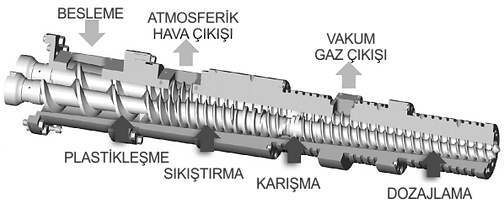
(1) Feeding Zone
(2) Transition / Compression Zone
(3) Dosing / Pressure Zone
There are three main regions.
Screws are typically classified in two basic different designs:
(1) Three Zone Screw (also called "measuring screw")
(2) Mixing Screw, When considering processing aids color and additive masterbatches (as well as pigments and fillers), the importance of mixing becomes obvious.
Most of the screws are nitrided to provide basic wear resistance, but they are also coated with a wide variety of surface coatings to provide greater wear resistance or chemical resistance.
Moving the material forward (and creating the necessary pressure in front of the mold)
Heating and melting, mixing and homogenisation of melts are typical screw tasks.
Helix Angle:
The arc trace formed by a point on a rotating cylinder is called "helis".
Helicals are bidirectional, right and left. To determine the direction, it is sufficient to tilt the thread / screw and look across. In the screw cross section, if the slope direction is on the right side, it is defined as ‹right helix, if it is on the left side‹ left helix. In extrusion mechanical technique, helical grooves (screws) are used for movement and force repulsion, to convey the polymeric material to the front (head) with pressure.
Helical mechanisms are less sensitive to geometric deviations and are used especially in applications with high speeds. The angle of deviation from the screw center vertical axis is equivalent to the helix angle.

Feeding Area:
Screw feeding section: it has deep channel gaps to take the material from the feed throat and carry out the main task of conveying solids. This region is particularly important as the total exit velocity of the extruder is directly dependent on the solids transport velocity in this region. To obtain the conveyed solids, the material must "stick to the barrel and slide on the screw". Proper temperature control is essential to achieve this. For example, if the feed zone is set to the wrong temperatures, it is possible for the material to move around the screw under the feed throat without any tendency in the direction of travel. The feed section is the region where many problems can occur and a skilled operator can push the screw through accurate temperature control of the screw root, feed section / barrel / furnace. It is the region closest to the motor to the feed point, where the screw channel depth is the most. It is the first part of the screw where the polymeric material encloses the sleeve. It makes up 25-30% of the screw length. In this area, the root depth is fixed. Thanks to these teeth, the plastic material is taken from the hopper by providing a certain pressure increase and pushed forward towards the hot areas. The friction between the material and the screw is also the lowest in this area.
Transition / Compression Zone:
The cavities of the compression section gradually change from deep to shallow. Here, the material is compressed and melted from 5D to 10D. It is the region where the polymeric material (s) now begin to melt. Screw groove depth is lower, melt-barrel friction is higher. The material (s) begin to combine with each other and gasses out. With the enlargement of the screw thread gap or the sudden increase in the screw channel depth, back suction chambers are created. Corresponding to this point on the screw, the gas that comes out is removed from the material by opening the channels on the barrel (vent opening). While this happens spontaneously with air pressure at these points, gas evacuation can be supported with vacuum. Especially, if additives are added to polymers, it is not suitable to process in ventless extruders as volatiles will not separate from the polymer and pass into the final product in the form of bubbles. A vented extruder should definitely be chosen.
Dosing / Pressure Zone:
The measurement section is the last section and has the shallowest flight depths. This shallowness is necessary to create the required pressure before the mold. It is the last zone where the polymeric material (s) now melt and come after mixing and will now be evacuated from the barrel. In this region, the diameter of the screw is the largest, in other words, the depth of the screw channel is the lowest. The ratio of gear pitch volumes at the head point (last) to the gear pitch volume at the screw feed point; It is defined as the screw compression ratio. It is common to see this ratio between 1 / 1.5 and 1/4. The pressure starts to increase as it moves away from the feeding zone with the lowest pressure in the barrel, and the value where the pressure is the highest is reached in this final zone. This pressure provides the pressure / push of the molten polymeric material in the barrel from the head to the next unit (mold etc.). This high pressure needed; It can be increased by external interventions (excluding screw structure) such as reducing the number of drain holes (nozzle) diameters / gaps in the head, reducing the number of nozzles by clogging some of the nozzles, reducing the temperature of the heat in this region compared to the transition / compression zone, reducing the filter / sieve pores if there is an application area. These discharge points, defined as nipples, are also known by taking uddles. Some screws have a "tapping" application at the final point in order to increase the pressure in the dosing / pressure sections. In these hammer-tipped screws; The friction of the polymeric material to the barrel along the ram is maximized, which means; improves the mixture. Some of the heat required for the plastic to melt is provided by the rotation of the screw. The higher the rotation speed, the higher the temperature. Even if the machine can rotate the screw rapidly by being high, it is more appropriate to adjust the screw rotation speed in accordance with the press time. Even the screw rotation speed should be reduced to the lowest possible value.
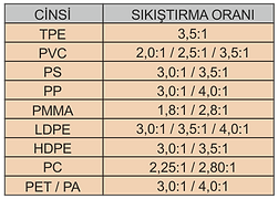
Screw Compression (C/R) Ratio
It is the ratio between the feed channel depth and the measuring channel depth.
The compression ratio of a three-zone screw can be considered as the most basic parameter when processing different polymeric materials with different viscoelastic properties.
This ratio is typically between 1.5:1 and 4.5:1.
Some polymers work better on screws with a compression ratio of 2.5:1, while other materials work better on screws with a compression ratio of 4:1. Generally, general-purpose 2.5-3:1 ratio screws are used, which are suitable for a wider range of materials.
This compression ratio corresponds to the depth of the channels. It is important to note that this compression ratio does not indicate how much shear the screw will shear through the material, and two screws with the same compression ratio can have significantly different output speeds. And these depths and The compression ratio has no meaning for the barrier screw.
C/R has often been used as a basis for adjusting the melt temperature in the past, and polymers with higher processing temperatures have been operated with higher compression ratios. Screws are designed for a given speed based on expected peak output and expected head pressure, which is usually within the extruder's capacity. While screws typically have a wide operating speed range, it is not an infinite range and can run poorly at speeds much higher or lower than their design speed.
Designers often they often evaluate whether the C/R should be 2:1, 3:1.
The polymer absorbs the shear energy from the rotating screw, and the lower the output, the more energy or melting temperature per unit of output, and vice versa.
The screw with 0.500 inch feed depth and 0.200 inch measuring depth has a C/R rating of 2.5.
Screw with a feed depth of 0.375 inches and a measuring depth of 0.150 inches It has a C/R value of 2.5.
How accurate would it be to expect these two designs to show the same performance. As a result, simply specifying C/R doesn't say much about the performance of the screw.
This is why C/R makes even less sense with the popularity of barrier screws that completely separate the melt and transport functions. Most barrier sections have a 10:1 feed depth to discharge depth ratio, but they provide a lower melt temperature at the same outlet than a conventional vane screw with a 3:1 ratio.
Every polymer, every extruder and every process requires a different design to optimize performance. The first thing to consider are values such as horsepower, screw speed, hole size, L/D. Then, process requirements such as desired melt temperature, output, need for evaporation, homogeneity come into play. Finally, the thermal, rheological and solid particle properties of the polymer must be considered.
Screw Length, Diameter (L / D) Ratio
It is the ratio of the length of the screw to its diameter. Screw lengths are mostly produced by the manufacturers.
by each of them in their own way. Some manufacturers generally refer to the wedge, some from the end of the wedge, and some refer to the middle of the feeding throat.
L/Ds are typically between 24:1 and 30:1 for profile extruder screws where flexibility is at the forefront of extrusion output, while for high output screws (e.g. barrier screws for pipe and sheet metal) it can be 35/38:1.
Generally 30:1 and above in extrusion machines,
In injection machines, it should generally be 20:1 or higher.
However, when the screw diameter is selected larger in plastic injection machines, the L/D ratio drops to 16:1. This reduces the melt injection weight in the screw proportionally. In order to balance this decrease, additional pitches are made in the feeding section and the amount of melt is slightly increased.
Advantages of large L/D ratio:
Shorter cycle time due to increased injection rate, less mold closing time due to less melting temperature requirement, less pressure and unwanted temperature changes, better color mixing and energy saving. As a result, the L/D ratio of the machine to be selected should not be lower than 20:1 and barrier screws with high mixing sections should be used.

Extruders typically have a conventional 20:1 L/D ratio. 24:1 L/D are considered "long". But these values of the 1960s evolved over time, extruders got longer and 30:1 to 38:1 L/D sizes became the industry "standard". In some extruders, 40:1 L/D ratios have even entered the industry for special purposes such as dual venting, compounding or high speed processing.
Extrusion lines with longer length and higher L/D ratio may seem attractive at first glance, but these attractive dimensions can also negatively affect overall performance. Just as an extruder size and drive combination is chosen, the L/D ratio must be carefully considered. Everyone wants the highest output from their extruder, but if the ejected material is too hot or deteriorated, then it shows that focusing on speed in that extruder should actually be relegated to second place. Data such as diffusivity, power coefficients, melting points, head pressure, viscosity and crystallinity are arguments for the evaluation process.
Some polymers melt much easier and faster than others. Also, some processes typically have lower head pressures while others have much higher discharge pressures. Intrinsic viscosity varies widely among polymers, and some do not carry significant shear. As a result, screw performance can be optimized in a variety of L/Ds rather than any standard L/D.
A screw that is too long for the general machining situation can actually limit output, reducing efficiency. Limiting factors are usually deterioration of the polymer, color shift, loss of additive effectiveness and high melt temperature. The most basic determining criterion is the Tg, Tm values of the polymer. For a readily melting polymer, the melt length should ideally be shorter because excessively long transitions can actually reduce the melt rate. The same goes for pressure development. Commonly used melt pumps are there to keep the discharge pressure high and constant, greatly reducing the need for screws with long measuring sections.
Regardless of the L/D, the feeding sections of the screws are of approximately equal length. The rest of the screw is devoted to melting and pumping. The deeper the screw channels or the higher the specific output, the longer you need to develop the necessary pressure to complete the melt and push the polymer out of the mold. However, as L/D increases, limits come into play in increasing output. Usually these limits are due to the inability of the feed section to deliver more polymer. For smaller diameter screws, this limit is usually determined by the screw strength. On small screws you can go reasonably deep in the screw channels, but on large extruders the feed efficiency decreases as the channels get deeper until there is no further increase in output.
Three Zone Screw
This screw has three different sections, typically 20D and 28D in length, namely the feed section, the clamping (or transition) section, and the metering section.
(1) Feeding Zone:
In the feeding zone, the granular, broken or powdered solid material is transported and pushed into the compression zone. In this area, the screw flow depth has been kept quite wide in order to provide sufficient flow even if the material is of low density.
(2) Compression Zone:
In the compression zone, the material taken from the feeding zone is compressed. Plastic raw material is melted thanks to heaters, it is made homogeneous by the rotational movement of the screw.
(3) Measurement Zone :
The temperature of the material that has become homogeneous is raised to the temperature to be injected (processing temperature) and the material becomes ready for molding.
In a vented extruder, the screw / barrel length is longer with the internal vacuum degasser. This length allows for the formation of two more parts, namely degassing and decompressing, in addition to the three parts mentioned above.
With three-zone screws, for the low and medium output range, as well as slip-sensitive materials such as PVC, are widely used.
For some polymers, it is not necessary for the screw to consist of three regions, and two or three of the regions can be combined. The important thing here is to know that the screw design depends mostly on the type of material to be processed.
Accordingly, the screw types
(1) General thermoplastic screws
(2) Elastomer screws,
(3) Pre-plasticization screws,
(4) It can also be classified as special type screws.
The differences between these screw types are due to the depth of flow in the feed and metering zones,
the compression ratio, the screw stroke, the length of the screw itself, and the area
It is due to their length. Compression ratio: the volume of the screw feed zone,
It is called the ratio of the measuring area to its volume. 1/2 - 1/4 ratios are often used.
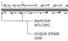
Barrier Screw
If a three-zone screw cannot complete the melting process and higher throughput rates are required, a "barrier screw" can be used. This screw has a secondary shallow barrier that is undercut in the channel and allows only completely molten plastic to pass through. Available in many different designs, but all aim to provide higher output rates at low melting temperature.
Screw Cleaning
Manual cleaning using solvents, wire brushes, abrasive tools and blowers is the most common cleaning operation of choice. Sometimes this cleaning is done by sandblasting. However, all cleaning operations in this type leave unnoticeable marks on the screw surface. These traces become more evident over time as the number of cleaning operations increases, and eventually, damages occur on the screw. These unsuitable cleaning methods will cause the screw to become dirty and get dirt faster.
During the extrusion process, the polymeric melts accumulated in the traces on this screw surface will burn, and will accumulate in the pre-mold filters and cause the clogging (filter filling) to accelerate. If precise measurements are made, reductions in machine efficiency can also be seen.
In the extrusion of thermoplastics and thermoset plastics, deteriorated material deposits on the screw are also effective in quality loss. The effect of screw cleaning is great on clean, smooth extrusion output and short transition period in color transitions by holding polymeric, rubber residues, adhesives, color and additive masterbatches to these traces.
Particular attention should be paid to the careful and sensitive cleaning of the screw tips, for a quality product and long service life.
The most effective method that can be applied in screw cleaning is the pyrolysis process.
Pyrolysis Process:
It is a thermochemical process that can be easily applied to any organic product. It consists of the words "pyro" meaning heat and fire in Greek and "lyse" meaning fragmentation. The process of thermal cracking of organic materials at high temperatures and in an oxygen-free environment is called pyrolysis. This process is the separation of carbonization gas and carbon from the polymers at a temperature of approximately 430 ° C, and the removal of the screw (whatever machine part such as strainer, mold) from the metallic surface. The pyrolysis process, which includes precision, cleaning quality, cleaning time, reliability, energy efficiency, environmental compatibility, is followed by the thermal cleaning (oxidation) stage.
The pyrolysis process is almost all equipment imaginable; extrusion screws, filters, mold, runner components, granule nozzles, mold plates, static mixers etc. can be applied to.
Organic products in the main reactor are thermally degraded at 300 ° C to 1000 ° C in an oxygen-free environment. Organic products that turn into gas phase as a result of thermal decomposition arrive at the catalytic converter unit. At this stage, the process is accelerated with the unit acting as a catalyst. Gases that can be condensed at the appropriate temperature in the auxiliary reactor zone are converted into pyrolytic liquid, LPG, carbon black and paraffin.
Thermal decomposition in the pyrolysis event takes place in the following stages:
-
100 ° C -120 ° C Absolute drying process is experienced.
-
120 ° C -250 ° C Disoxidation occurs, desulfurization (decomposition of oxygen, sulfur from metal and polymeric dirt on it).
-
380 ° C Carbonization and enrichment phase occurs.
-
At 400 ° C, the bonds of Carbon-Oxygen and Carbon-Nitrogen compounds begin to break.
-
400 ° C - 420 ° C All substances begin to turn into Pyrolysis oil and tar.
-
600 ° C All materials are cranked to heat-resistant materials.
-
Above 600 ° C, there is a cranking process and aromatics and ethylene are formed.
After the pyrolysis process, in which screw cleaning can also be done, pyrolytic oil, carbon black, paraffin gases that cannot be condensed during the process are obtained as by-products. Gases released are more valuable than natural gas in terms of calories. It can be used as a fuel to meet energy needs in many different sectors.
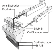
Co-Extrusion (CoEx) Technique
It is the process of laminating two or more melts in the same mold to produce multi-layer film in one piece.
At least two extruders are required for co-extrusion. However; number of extruders, extruded may not be in the number of layers.
In other words, two-layer films can be made with two extruders, as well as three- or four-layer films, even films with a much higher number of layers than the model of the mold.
This is because current feed block technology allows melt from an extruder to be separated into two or more layers in the die, in the final coextrudate.
Each ply retains its original character but is joined into a piece of composite material. An extruder before extrusion The properties of individual materials can be changed in the feed, but the result is a homogeneous product.
Not all plastics are suitable for co-extrusion because some polymers do not adhere to others.
For this, it is necessary to be knowledgeable about the compatibility of polymers. However, the application of a conductive middle layer can often solve this problem.
Plastics with different melting temperatures are not suitable for this process because degradation occurs in the lower melt material.
Finally, PVC and acetals should never be co-extruded due to the potentially violent reactions that can occur when combined.
To reduce the raw material cost, co-extrusion is one-to-one.
Especially by keeping the fillers in the middle layers, both the cost is reduced and the surface smoothness is not compromised. In addition, in the application of color and additive masterbatches, longer-lasting and more vivid results are in question.
Advantages include high quality monolayer extrusion coatings with greater line speed and width variants, savings in original raw materials, reduction in the number of steps required in the overall extrusion process, use of specific polymers in specific layers. performance enhancement can be demonstrated.
In addition to these, there are also some disadvantages.
For this process, all polymers must have similar melt viscosities to maintain laminar flow.
Viscosity differences cause weakening of the layer. However, it can be tolerated more or less depending on the material location in the composite structure.
Requires more advanced extruder structure and operator knowledge. This means the extra maintenance cost of the equipment.
Considerable planning is also needed in system design.


Ekstruzyon Ekipmanları
Agromel Machine:
It is the machine that performs the process of shredding, drying and adding density to the plastic material before extrusion. The rotating and fixed blades in the boiler rotate at high speed and close to the ground, with the help of friction formed, by heating the plastic, it separates it into pieces and removes its moisture, then its density increases by shocking with water, and thus, more efficiency is obtained from the feeding of the extruder machine.

Feed:
It is the chamber where the main machine receives the polymeric material for the extrusion process. It can be used with a dosing unit as well as the polymeric material can be poured directly into the screw-barrel with the screw movement and gravity force under the chamber. The dosing unit is the premix of the complex polymeric material (premix) by hand in a mixer or a vessel. It provides convenience and control in the workflow by eliminating the preparation work.
Extruder Machine:
The basic unit of the plastic product formation process is the extruder machine. In this unit, the raw material is first exposed to heat in a beehive/furnace and converted into molten form, and it is transformed into a workable structure by providing forward flow with the screw/shaft movement inside.
The main functions of an extruder are to melt the plastic granule particles and mix the resulting molten polymer to obtain a homogeneous melt. This is done by transporting the material through a heated barrel with a rotary screw. Commercially used extruder bushings are usually 3½” (90 mm) to 6” (150 mm) in diameter. Screws are tailored to the specific characteristics of extruded materials and process parameters. The length of the screw is greatly affected by their diameter. Screw length to diameter (L/D) ratios are generally in the range of 26:1 to 30:1.
It is important to ensure that the flow out of the extruder is well controlled and stable with variations in screw rotational speed not exceeding ±1%. Improper control of screw speed often results in undesirable pulsating flow, which can cause periodic changes in film thickness in the machine direction. The measuring section, or the last section of the extruder, is designed to guarantee precise dosing of material from the extruder. To achieve the above, the gap between the screw and the barrel is too small. This creates another challenge because it is difficult to maintain a constant clearance between the rotary screw and the barrel.
To overcome the potential problems outlined above, a melt pump is commonly used downstream of the extruder. The pump is a positive displacement device that produces a consistent flow regardless of the extruder's discharge pressure. The pump takes over the pressure generation job, relieving the workload on the extruder. The reduced extruder head pressure translates into savings in energy consumption, a drop in melt temperature, and less wear between the barrel and screw. (Detailed explanation is available on extrusion equipment) .
Static Mixer:
It is used in the processes of mixing the polymer melt homogeneously and effectively before pouring it into the molds and keeping the temperature constant. Static mixers increase the reliability of the injection molding process, reduce the amount of masterbatch used and optimize the injection molding process overall. They provide an effective solution to color lines problems.
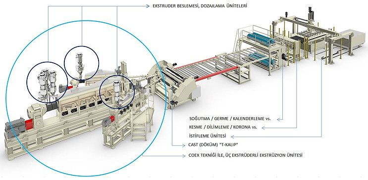
Flat (T) Formwork System:
It can be said that the die system is the heart of any extrusion line. The die system is formed by the coextrusion feed block, flat die and melt transfer adapters that transport the different molten polymers from the extruders to the feed block inlet ports. The quality of the co-extruded film and the efficiency of the process largely depend on the design and performance characteristics of the die system.
The primary function of the die system is to create a multi-layer film that is uniformly distributed across the width of the die with thickness variations on the film and thickness variations at each layer within industry accepted tolerances (±15% to ±20% for the total thickness and each layer). There are melt transfer adapters from the feed block upwards. The design criteria of this capillary system should consider parameters such as material residence time, pressure drop and temperature control. For example, an excessive pressure drop can be addressed by increasing the pipe diameter; however, this will increase the residence time of the material and increase the likelihood of the material deteriorating. Also, correct wall thickness sizing and proper heater properties are required to prevent pipes from heating or cooling the melts they carry. It is up to the designer to find the appropriate balance between all these variables.
Coextrusion feed block:
It arranges the different melt streams in a predetermined sequence of layers and produces as many melt streams as the layers were in the final co-fold. Once this is done, each flow adopts a planar geometry, meets its neighboring layers, and a final planar co-extrudate (coextrusion) is formed.
Coextrusion feed blocks fall into two categories:
Fixed and variable geometry blocks. Upstream of these blocks are the selector plug or selector pulley. This cylindrically shaped removable part is responsible for directing each melt stream together to its final position in the extrudate. The plug divides these currents, if necessary, by a material that feeds more than one layer in the structure. If a different layer order is required, it can be achieved simply by changing the plug.
Fixed geometry blocks:
It is most effective when the production line is divided into only a few different products that are similar in their rheological behavior. However, it is important to note that these blocks have removable flow inserts that can be machined or replaced as needed to handle a wider range of materials.
Variable geometry blocks:
ideal for co-extrusion of high value-added materials or when the scope of the production line is more diversified. Generally, these blocks have movable internal components that can adjust the width distribution of a single layer before meeting with neighboring layers and/or its velocity, thereby affecting the shear rate and viscosity. Thus, coextrusion-specific problems such as sheet distortion and interfacial instability can be overcome by adjusting the feed block.
Despite all the capabilities of coextrusion feed block technology to address the flow anomalies inherent in coextrusion flows, producing an optimal co-extrudate is only possible if the feed block works in conjunction with a properly designed die to handle a coextrusion flow. The perfect synergy between the die and the feed block is what will guarantee a high quality product.
A well-designed die should ensure that the flatness of each sheet is maintained within a tolerance of ±15% to ±20% during the spreading process of the co-extrude from the feed block. It should also be designed so that the residence time is not excessive to avoid degradation problems or in some cases to avoid unwanted heat transfer between layers. The die should also be designed so that the pressure drop is maintained at a normal level within the extrusion process.
It is also important that the mold has the appropriate size, sufficient steel mass, and appropriate mechanical design to ensure thermal stability and to minimize the problem of shelling of mussels, which manifests as excessive deformation of the mold lips when mold occurs. subjected to the high pressures inherent in the extrusion of thin films. Recent advances in mold technology have increased the efficiency of cast film production lines. Special references can be made to so-called inner decks. Decks placed at either end of the mold allow for changes in film width and consequent reduction in trim. They are fixed or adjustable and can exceed 20 inches in length.
Recently, edge encapsulation technology has been applied to reduce the negative financial impact of material waste when co-encapsulation technology cannot be recycled. The previous figure shows a tape of a single material extruded side by side with a co-extrudate. The encapsulation material is low cost, recyclable and has high mechanical properties. The encapsulation material essentially forms the flooring, which allows it to be reinserted into the manufacturing process and huge savings in material cost. In addition, the edge encapsulation technology is fully compatible with the built-in deckle technology.
Filter / Strainer:
The purpose of the filtration system is to prevent the downstream passage of melt impurities and/or gels formed during the extrusion process. Proper control is essential at this stage to avoid melt contamination. The most common filters are those containing metallic mesh. The case housing the filter media must be able to bear the forces exerted by the polymer flow when subjected to the maximum pressure allowed by the extrusion process.
They are used to clean polluting materials such as sand, metal, non-melting plastics, which remain in the melt and reduce product quality, with special filters attached to the sieve mesh.
Filter plates can be moved with hydraulic units or nitrogen gas units. It is the unit that supports reaching the maximum level in product quality and efficiency with special insulated resistances and sensitive heat control. It is also a factor in increasing dosing pressure. The need for change arises when the sieve pores are filled during the process. In this process, Strainer Change Stops are also added to the process, resulting in loss of production. There are automatic filters with rotating wheels for this. These systems, which allow the filter change in an uninterrupted production flow, are initially expensive investments.

Dosing:
It provides flow to the hopper in accordance with the ratio of the component polymeric material in a unit amount of complex. There are basically two working systems, gravimetric and volumetric.
Dosing Unit Preference:
The following data must be known when selecting the dosing device for the injection machine. The minimum and maximum product weight to be produced in the machine must be known (kg/hour). Minimum and maximum dosage rate of each additive or dye to be dosed (depending on product weight) (%).
Each additive or dye to be dosed (depending on whether it is granule, microgranule, crushed, liquid or powder) bulk density , part shape and temperature
Total print time (seconds)
Time to receive goods (seconds)
Throat flange dimensions at the injection receiving point
The necessity of automatic transport of the material to be dosed to the chamber
Within this information, details such as the screw capacity of the dosing device, the capacity of the chamber where the dosing material will be placed, the dosing device throat type, the control panel can be determined and the device can be selected.
Dosing or Blender?
The Gravimetric Multiple Dosing and Mixing Device, called Blender, is a complex device that gravimetrically dose many materials (including the main material..) and mixes them in the same device, as can be understood from its description. In other words, the Blender provides precise dosing and homogeneous mixing of different materials at the desired rate. Each material in this mixture, which is defined as heap, is mixed at the desired rate.
With this feature, the Blender is not affected by volumetric errors caused by the density and shape changes of both the main material and additives. On the other hand, it is absolutely not affected by the speed changes of the plastic processing machine, as it always keeps the desired weight stack in the throat of the processing machine.
The biggest advantage of using blender is that it is the definitive solution in the use of crushed raw materials. Due to the unavoidable density change of the crushing raw material, in principle, the dye addition rate must be constantly changed. Dosing devices cannot do this. However, the Blender first weighs the crushed material every time it starts to prepare a batch due to its working principle. Accordingly, by adjusting the main material and crushing ratio, it provides a very sensitive mixture and prevents the use of unnecessary raw materials and dyes.
Another advantage of using a blender is that it can be directly connected to the screw neck of the plastic processing machine, or it can be mounted on a platform and used next to the machine or centrally.
(1) Gravimetric Dosing:
With the operation of the screw feeder, the system is weighed in each unit of time and the amount of decreasing material is calculated.
It means dosing with continuous weighing. of raw material bulk density It is a dosing method in which the weight of the material is constantly weighed in order to eliminate the quality, production and color errors experienced due to the change in production.
The batcher is designed to add any additives or dyes to the plastics processing process. In the simplest sense, the dosing device is a device that is connected to the point where the main material of the plastic machine flows with the screw neck of the chamber, with a special flange. At this point, other additives can be dosed in the same way. However, each can be dosed independently of the other.
This amount is compared to the target value and the motor is commanded for the appropriate calculated speed. It is suitable for continuous dosing of granular, powder, earthy, fibrous and flaked materials. Since it is a continuous weighing, the feeding amount is constantly monitored and adjusted. Gravimetric method should definitely be preferred in processes where precision and raw material consumption is important. It can be worked with 0.1% sensitivities. In the processes carried out with this sensitivity, both the raw material, which is the system input, is saved, and the efficiency and quality are increased and continuity is ensured by obtaining homogeneity in the system output.
It controls the amount of material fed into the extruder by weight weighing, not by volume. The system is more precise than its volumetric contrast and has a reduced error tolerance of ±0.5%. In most cases, the film is manufactured with materials in which a base polymer is blended with one or more secondary components. In the most advanced production lines, this blending is carried out in-situ. Particular care is required to prevent premature melting of the granule particles, especially when materials with low melting temperatures are processed or the granule size is small. .
Dosing devices cannot follow base material changes. Because there is no system that follows the main material gravimetrically. For this reason, volumetric or gravimetric single dosing devices do not give any guarantee in terms of spent plastic mixture. However, for example, in injection machine applications, the base material weight is certain and if a sensitive dosing device is selected, there will be no homogeneity problem caused by the base material change.
They should be preferred in very sensitive dosing applications and for statistical raw material tracking.
General reasons for choosing gravimetric dosing:
Cost: Gravimetric dosing devices amortize their investment cost in a period of 6 months.
Gain: Waste is reduced, production errors are reduced, up to 50% additive/dye savings are achieved.
Stability: Especially gravimetric dosers working with stepping motors make constant dosage at each additive ratio.
Function : The gravimetric dosers working with the load-cell system can be adjusted very easily. It is sufficient to enter the product weight (or extruder capacity) and additive ratio. Color change is done in a very short time.
Design : With gravimetric dosers with modular structure, additive dosing can be done in many different capacities and shapes.
Follow-up: Since gravimetric dosers work by weighing continuously, consumption reports can be obtained in processes such as shifts/days/months.
Savings: Thanks to garvimetric dosers, homogeneous and economical paint/additives are used even if highly recycled materials are used.

(2) Volumetric Dosing: It is an older method than gravimetric dosing. So it is more known. The most obvious difference from gravimetric is that there is no weighing in the process. Instead of weight control, there is a feed screw that rotates at a constant speed. At the beginning of the process, the feed screw is preferred according to the material density and the desired feed amount (kg). Then, according to the density, "how much volume a screw pitch will give the desired kg at the end of the given time" is calculated and the system works at a constant speed accordingly.
Since the speed is constant, even small differences in material density affect the amount of material dosed. This means a rough weighing. It works with an accuracy of about 10%. The homogeneity distribution can draw a wavy graph in the system output.
Its cost is much lower than gravimetric dosing. This is the most important reason why it is preferred.

Melt Pump :
The extruder machine may not have sufficient effect on conveying the melt into dies at constant pressure and volume.
For this purpose, melt pumps are used. The melt pump is not a mixing or melting device, but it is extremely effective at creating pressure and delivering the melt by measuring it. Internal pressure imbalances and extruder fluctuations caused by the speed changes of a sufficient amount of polymer extruder screw are eliminated by closed-loop control of the speed of the screw and pumping with much higher and constant value pressure in the die direction. The pressure change experienced with the melt pump is shown below.


Vacuum Pump/Box:
In addition to preventing material loss, it prevents damage caused by molten plastic and uncontrolled gas output. It does not cause any problem in product quality, and it prevents quality problems caused by vacuum gas and moisture jams. Increased extruder pressure increases porosity. Minimizes annoying and costly timeout due to vent port blockage, Precise tolerances, Removes moisture and gas from the melt.
It removes entrained air between the surface of the primary quench roll and the film to minimize the air barrier between the hot web and the roll. This air barrier, if not reduced, acts as a thermal insulation pad that blocks the film cooling process. The box also reduces the amount of neck and air gap in the film and allows higher line speeds to be used.
The vacuum box can be combined with an air knife or an air baffle to further increase mesh cooling.
Automatic Display Control System: The inline measurement and control of the film thickness distribution across the width is the function of the gauge control system or APC (Automatic Profile Control). When the flexible lip on the mold is manually controlled and the production process is well tuned, the film thickness variations will be in the range of ±3% to ±5%. In automatic mode it is possible to reduce these variations by half. The figure below shows an automatic mold with the automatic control module mounted on the flexible body of the mold. Thermal converters or thermal bolts form the module. The distance between the bolts is typically 1.125 inches. The instrument control system includes a radiation emission unit and a control console.
The radiation unit moves the machine in a diagonal direction, scanning the film in cycles (measured in minutes). Commonly, the radiation originates from a beta ray source; however, x-ray and infrared sources can also be used.
Generally, the film thickness is determined as a function of the film radiation absorption rate. Thus, variations in absorption rate translate into film thickness variations.
The control console is the interface between the control system and the automatic mold. Each setpoint or thermal translator on the die is spatially related to a location on the film. This is called mapping. The control system powers the thermal converters as needed and the lip gap is regulated by the thermal expansion of the actuator.
An important variable associated with APC is the time constant. It is defined as the time required for an adjusting element to extend 62.3% of its maximum elongation. The shorter the time constant, the more responsive the system will translate into gains in efficiency.
Granulator/Crusher:
For the cutting and sizing work of spaghetti lines after extrusion, the unit that works with the rotary blades system and gives the product a granular form is the granulators. The semi-form material works with the system of cutting between offset rings rotating at approximately the same speed as the machine exit speed and ejecting the material in particle size with centrifugal action. Crushing and powerful grating units are units that work with the same method, mostly for recycling and reuse. Crushing and strong graters are used to provide volumes that have lost their form as a product but can be reused in the feeding unit.

Corona unit:
To facilitate the adhesion of inks or coatings to the film surface, it is necessary to apply a surface treatment. Corona treatment is the most widely used of the available methods. Corona treatment is used for the preparation of films and various surfaces for printing or gluing. The corona unit sends electric sparks to the surface to be treated, roughening the surface and making the ink or glue adhere better to the surface. provides.
The corona treatment increases the surface energy of the film and therefore the surface tension. The system includes a power supply and treatment station. The power supply converts 50/60 Hz plant power to much higher frequency power in the 10 to 30 KHz range. This high frequency energy is fed into the treatment station and applied to the film surface via two electrodes, one high potential and the other low potential, through an air gap typically ranging from 0.5 inch to 1 inch.
When the high potential difference produced ionizes the air, the surface tension on the film surface increases. The corona treatment can be done either in-surface or as a separate downstream treatment after the film has been produced. Particular attention should be paid to the generation of potentially toxic ozone if performed on the surface. In some cases, it is necessary to provide a ventilation system in the production area.

Chiller /Cooling unit :
It is the "Outdoor" unit used to keep the temperature of the machine inlet water used for cooling of machinery and equipment stable.
The main purpose depends on the principle of taking the heat from the hot water coming out of the hot units such as the machine and mold, reducing the temperature of the water and giving it back to the machine. It can be in different working principles as water or air cooled. Water-cooled chillers are more efficient. In this system; Cooling tower, condenser and make-up water pumps, reservoirs are essential components. It is in smaller volumes that can be placed indoors.
Air-cooled chillers, on the other hand, are preferred when aesthetic and environmental conditions or water access restrictions exist.
difference; This is because water-cooled chillers, or rather, cooling towers, use a stream of moist air, while air-cooled chillers use a stream of ambient air. Normally water-cooled chillers are cheaper and more efficient, although they have the disadvantage of high water consumption.
The benefits of air cooled chillers are as follows;
There is no cooling tower and water wastage.
It is low maintenance cost and easier to use.
Also, there are no chemical costs.
Cooling capacity is the main guide for chiller selection.
While a water-cooled chiller is more energy efficient, it has a disadvantage over an air-cooled chiller in terms of installation cost, maintenance cost, number of equipment and some other aspects.
The (ChillRoll) primary quenching roller is the "Inner" unit consisting of a secondary roller, a motorized roller positioning system for smooth vertical and cross machine direction alignment of the rollers, and in many cases a vacuum box and/or air knife.
Rolls are typically chrome plated to achieve a better surface finish and increase the heat transfer process during film cooling. The coolant is usually water circulating inside the cylinders.
The primary quench roll cools one side of the film and the secondary roll cools the opposite side of the film. The mold is placed above the primary quenching cylinder at an angle ranging from 45° to 90°. The distance between die lips exit and roll ranges from 0.8 to 2 inches. The cooling system allows the line to run at high speeds. As the line speed requirement increases, so do the diameters specified for the rollers.
The rolls must be perfectly aligned with the web to ensure uniform tension and minimize thickness variations across the width of the film.
Also, the angular velocity of the rolls must be well controlled to avoid film thickness fluctuations in the machine direction.
The use of a vacuum box attached to the die fixed body is required in certain applications, such as Cast PP, where more efficient cooling is required. PP materials tend to form crystals which, if not aggressively cooled, eventually lead to hazy films.

Thermocouple:
Temperature control and heat measurement is the most important process control operation of extrusion. Equipment used for this job are thermocouples. And thermocouples can come in a variety of construction and measurement techniques. The compatibility of the preferred thermocouple with the machine is the first step to be considered. Thermocouple is a kind of temperature sensor. It consists of two different conductive materials and is defined as a «Thermal Couple» in this context. The two ends of these materials are joined on the side that will be exposed to heat. A tension is obtained because the other free ends are colder. The voltage varies depending on the type of material used and the amount of heating of the junction point.
The hot spot value is determined by comparing the value at the known cold spot with the voltage values. Well; In order to learn the value of the hot spot, the value of the cold spot must be known. To eliminate the unknown cold point value, the compensation cable should be extended to a known point or a unit in the form of a thermostat should be included in the operating system.
Type definitions are made according to the type of material used in the thermocouple.
The most frequently used material pairs;
Copper-Constantan, Iron-Constantan,
Nickel Chromium-Nickel, Platinum Radium-Platinum,
It is in the form of Kromel-Constantan, Kromel-Alumel combinations.
Structures with different combinations will show a few °C different measurements, ie deviations, at the same measurement values, which means inaccurate measurements. This will lead to incorrect interventions. In thermocouples, the first edge is always positive. Color coding is available for this.
codes are both thermocouple and compensation applies to Thermocouple wires color code Define a few practical tips if it doesn't are available, which are in the compensation cable
not valid.


Winding unit:
In simple terms, rewinders are used to convert the extruded film into rolls of material. The wrapping process should be such as to preserve the properties and dimensions of the film when these rolls are unrolled and converted in other downstream processes.
There are three basic types of wrappers; surface winders, turret or center winders and center / surface winders. The surface wraps pass the film through the contact between a large diameter drum and a winding shaft pressed onto the drum with variable pressure. Turret winders or center winders are any winding machine that uses a drive shaft that runs through the center of the build roll or that uses chucks that support the core to drive the build roll. Finally, in the combined approach of a center/surface wrapper (or space wrapper), a small gap is maintained between the surface wrap roll or wrap-on-roll and the wrap roll. A central drive system drives the winding roll independently of the surface drum.
Films can be sticky or slip to some extent, have high or low elasticity, be thin or thick, the required roll diameter can be large or small; rolls can be narrow or wide, soft or hard. Wrapper technology is complex and the appropriate type of wrapper used in a particular application depends on all of the above variables.
The use of turret or center windings is typical in cast film applications. With this type of wrapper, the web tension decreases as the roll diameter increases. This is controlled by the rotation speed of the winding spindle. The rolling roll prevents or allows a small amount of air to be trapped between the layers. Second, it is recommended for wrapping high tack films or wrapping soft rolls.
Distributor rollers are used to evenly distribute defects (thickness variations) on the extruded film. The film moves sideways as it passes through the rollers to be wound. An alternative method is to move the cutter and rewinder back and forth relative to the film.

Control System:
The main components of the cast extrusion line are numbered and explained. These components do not act on their own, but are integrated and managed by a computerized control and control system. The main computer is the brain that combines and directs the controls of all line components in an orderly fashion.
The main tasks of the computer are:
To control the starting, closing and speed of the line;
Monitoring the weight of material fed into the extruders and controlling the speed of the extruders to maintain a constant yield;
To control all temperature zones and temperatures of all materials;
Coordinating the interaction between gauge control system, automatic die response and line speed;
To control the web tension; and
Store operational data and control alarm system to store and process all product recipes.
A good control system should provide operators with an easy-to-use graphical interface or monitor system.

Extrusion Production Lines
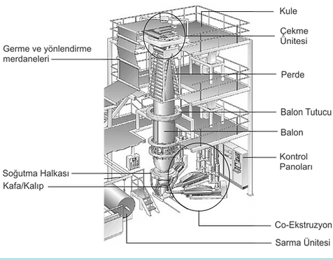
Blown Film Lines
They are production lines designed for use everywhere, covering a wide range of applications. 250 micron thick barrier films are the choice for a variety of products up to 10 micron HDPE garbage bags. It can be applied in the Co-Extrusion technique for the production of highly filled, non-transparent blown films. Blown film extrusion is the most common method for making plastic films, especially in the packaging industry. The process is based on the principle of extruding the plum and forming a thin film balloon that can be up to several times the initial (head) diameter, and then deflating this balloon into a flat film form. The film, which is formed as a closed double layer, is finished in three different final processes in the winding units. The film is wrapped as it is, in the form of a tube with both sides closed, It can be cut on one side with a width equal to twice the width of the winding by cutting one side, or it can be single folded in the double winding unit by cutting both sides. If desired, the film can be divided into several slices with a slicing unit and narrower width. movies can be created. With this process, usually polyethylene used.
Typically, blown film extrusion is performed vertically upwards, but horizontal and downward extrusions are also possible. Blown film generally has a better balance of mechanical properties than cast or extruded films because they have elongation in both the transverse and machine directions. The mechanical properties of thin film include tensile and bending strength and toughness. Almost uniform properties in both directions give the film maximum durability.
Blown film production requires lower melting temperatures than cast extrusion.
In the pouring method, the head temperature is about 220°C, while the temperature of the blown film is about 135°C. In addition, the blown production equipment cost is about half of the equipment cost of the casting film line. The final product MFI in blown film is about 1.0 g/10 min. This is one of the factors that makes the job of controlling the film thickness more complex and more difficult. In addition, with this low MFI value, the production capacity of blown film lines is lower than that of cast film lines. The products coming out of the blown film lines may be direct products, or they are mostly semi-finished / semi-formed.
As a product, greenhouse cover, tarpaulin, strawberry, watermelon, nematode, solarization, irrigation hose, insulation waterproof cover and layers can be given as examples. In addition, for products that require second and even third stage processes such as shrink, stretch, bag, bag, the first process stage takes place from this line.
It is the most widely used production method in the production of layers and plastic films with a thickness of less than 0.7 mm in recent years. In summary, the process is based on the principle of forming a thin tube by extruding molten plastic vertically upwards in a circular mold, inflating the plastic tube with the help of blown air with the mechanism placed in the extruder head, inflating the plastic tube in the form of a balloon, and wrapping the balloon in the form of a film with pulling and tensioning rollers.
With the effect of air cooling applied from the mold/head point, the transformation of the balloon from the soft form to the solid form is accelerated. This point line where the transformation takes place is defined as the «freeze line/line». In order for the thickness distribution on the formed balloon to spread evenly over the entire surface, a rotational movement of up to 360° is applied either from the lower end of the balloon, that is, from the head, or from the upper end, that is, from the drawing rollers.
Thus, the thickness difference that may occur at the die/head point spreads over the entire film surface and a balance is achieved.
The pressure inside the plastic balloon, the drawing speed of the cylinders, the cooling rate of the balloon are among the most important process variables as they affect both crystallinity and orientation.
More versatility is provided by the Co-Extrusion application.
More flexible equipment can adapt to more structural changes, allowing processors to better respond to market needs.
Better film quality is achieved.
It is noted that a greater number of layers yields a flatter film with more uniform properties.
Production takes place with lower material costs.
As more layers will be formed, lower cost filling in the interlayers, in the structures It becomes possible to reduce the cost of the film by adding materials.
Blown film extrusion is one of many polymer manufacturing processes. This method is used to produce commodity and specialty polymer films that are typically used in packaging such as shrinkage, stretch, barrier films (used to protect deli meat), frozen food packaging, and shopping bags.
There are many types of polymers that can be used in blown film extrusion, most commonly polypropylene and polyethylene (LDPE, HDPE and LLDPE). This method can produce monolayer films as well as more complex multilayer films that involve co-extrusion to combine multiple plastics into a single film.
Blown film extrusion can be complex, so now we will explain each step of the process in detail!
The first step is to melt the polymer in an extruder.
Polymer resin (granule size), mostly in the form of beads, is loaded into a hopper and fed into a heated channel with a screw.
The screw is used to move the polymer from the chamber to the other outlet end of the duct. Granular sized grains are gradually heated to melt. The heat profile is an important part of extrusion because the polymer can thermally degrade when overheated. When the molten material reaches the channel end, it is extruded from a die. At this point, blown film extrusion differs from other extrusion processes.
There are several different types of ring-shaped dies, the most common used in blown film extrusion, this is a simple circle die. The molten polymer enters the die head and air is injected through a hole in the die center to radially inflate the polymer into a thin tube many times its original, extruded diameter. It is this step of the process that can be adjusted to achieve the desired film thickness and width.
The hot tube film is then cooled, typically with high velocity air, and pulled upwards by equipment called pinch rollers. On most medium to large film lines, this vertical tube can extend several times into the air. As the film cools, it crystallizes at the so-called frost line. When the pipe reaches the nip rollers, above the line, the film is now cool enough to flatten and is then called a straight or collapsed pipe.
The film is then transported downstream by rollers for further processing (eg slit, printed, vented, formed into bags) and finally wound into rolls. Producing films using the blown film extrusion process has many advantages, including the ability to manipulate the mechanical properties of the final plastic based on the process conditions and the base polymer(s) used.
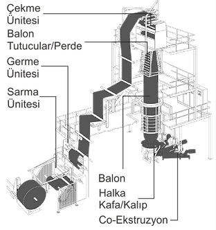
Cast Film Lines
The main argument of the cast film process is the flat 'T' die.
After extrusion, the melt comes out of this T die like a flat curtain and immediately flows onto the cold roller (Chill-Roll). Typically water-cooled and with a chrome-plated surface, this drum cools the melt by freezing. Process; It includes the principle of transporting the straight out melt to the final winding unit with suitable width rollers. Here the film is a single layer and all rolls are equivalent to the die width. Naturally The winding unit also wraps a single layer of film. If desired, various film widths can be created by slicing. Due to its rapid quenching properties, a cast film generally has much better optical values than a blown film. The melt flow index MFI for cast film is about 5.0 g/10 min. This value is a factor in achieving higher line speeds. Cast film lines can achieve production rates of up to 300 m/min.
The elongation values in the machine direction are much better than the casting process.
However, the film mechanical properties in the cross direction of the machine are much lower than those generated by the higher orientations experienced in the blowing process. Thickness control in cast film lines takes place automatically along the film width. A moving sensor controls the continuously advancing line and automatically transmits the data it receives to the head resistance and moving bolts and makes the necessary intervention. Film thickness variation is between about 1% and 2.5% and is much better than blown films.
Cast film line; It has gravimetric feeding, extruder, filtration and flat die system, cooling drum, automatic thickness control system, rolling, wrapping/slicing unit and optional corona unit components.
Co-Extrusion technique is dominant in cast film lines. It is possible to produce a variety of films, including stretch, silage wrap films, personal care films, oven films and high-definition films, nematode, greenhouse covers.
Cast films are used in food and textile packaging, flower wrapping, as photo album page protectors, as coating substrates in extrusion coating processes, or laminated to other materials in the formation of more complex films. Typically, the cast film process involves the use of coextrusion, which is the simultaneous extrusion of two or more materials from a single die to form a multilayer film. This is because in most cases the final application of plastic film requires performance that cannot be achieved if the film consists of only one material. For example, food packaging applications in many cases require the use of films with oxygen barrier properties. To meet the requirement, a high oxygen barrier material such as EVOH is combined with polyolefin materials in a multilayer structure. Co-extruded films are mostly seven-layer, but the use of more layers is becoming more and more common. The number of layers, their position in the coextrusion and their respective thickness are variables that vary depending on the particular application of the film.
Benefits / Limitations of Cast Extrusion
Unlike the blown film process, cooling the film by casting extrusion is highly efficient. This allows for higher production line speeds, resulting in higher production speeds with the product's superior optical properties. The degree of shrinkage and orientation is significantly lower in the cast film process than in the blown film process. This is the reason for the thickness distribution
on the machine the cross direction is more even with casting processes (with variations as low as ±1.5%). However, the film mechanical properties in the cross direction of the machine are lower compared to those obtained with the blown film process due to the higher level of orientation the film experiences in the blown process.
In cast extrusion, the edges of the film are clipped due to dimensional irregularities and/or poor layer distribution. As a result, the process can be adversely affected if the cut material cannot be recycled. The latest flat die system technology has minimized this problem by significantly reducing the amount of material consumed in extrusion processes. This issue will be discussed to some extent in the next section.
Basic Concepts of Casting Extrusion
In the cast film extrusion process, the molten polymer passes through a flat die system to adopt the final flat film shape. The die system is formed by the die and feed block (if the process requires co-extrusion), or simply by the die if the process is a single-layer extrusion process. The process begins with the feeding of plastic resins to one or more extruders via a gravimetric feeding system. The materials are then melted and mixed with extruders, filtered and fed into the die system.
Immediately after exiting the mold, the molten curtain enters the cooling unit where the temperature is lowered by a water-cooled cooling roller to "freeze" the film. The film is then passed down by corona treatment (if a manufacturing process such as printing or coating is required) where the edges are trimmed and the film is wound onto rolls. A description of the main components of a typical cast film line is presented below.


Compound / Masterbatch Production Lines
Basically, it consists of mixer, extruder, dryer and granulator units. Depending on the volume of production, agromel, feeding silo, sieve, crushing, dosing side elements may also take place in this process. While the raw material to be used in compound production can vary widely, LDPE, PP, SAN, ABS, partially PC, PET, EVA, rarely HDPE and others are preferred in masterbatch productions. Instead of the final product, the intermediate form product to be used in the final products, the raw material of the final product or the agent and color additives that will shape the product quality are produced from the compuand and masterbatch production lines. Process inputs basically consist of micron particle size powder or granular particles. It consists of extruding the homogeneous material obtained by mixing the ingredients manually or by mixing with a mixer, and then cutting the spaghetti product into granule sizes after the quantities are determined in the specified formulation. According to preference, granule sizes can be converted into powder form by grinding process. However, in any case, the resulting product is an intermediate form product.
Color masterbatch is a solid or liquid additive used to color plastics. It is a concentrated mixture of a pigment or additive encapsulated during a heat treatment into a carrier resin, then cooled and cut into a granular shape. Masterbatches allow manufacturers to color the raw polymer economically during the plastics manufacturing process.
The masterbatch production process is divided into two parts as “mono” and “tailor made”.
In mono production, the main or the most consumable colors are studied.
Tailor made is the matching of the mono colors obtained in various combinations, the formulation that is obtained or desired. color work.
The points to be considered can be listed as follows.
- Especially the fillings used in PVC production change the color tone.
- The difference in cable production methods affects the color of the paint.
- Not cleaning the machines well causes discoloration and scars.Stopping and running of machines may cause contact with material that was previously in the area outside the remaining flow path. This occurs as a trace problem in the product. In cases where machine contamination is suspected, a few prints should be made with only raw materials and the cleanliness of the flow line should be checked at every stage.
- First prints should be checked when machines are stopped and restarted for more than 10 minutes. Burning may occur because the material is exposed to heat for a long time.
- Especially in cases where there is a change in the raw material and micron used in film production, trial production must be done.
- When working at temperatures lower than the melting point of the carrier used, melting will not occur in the final product.
- Raw materials that absorb moisture must be conditioned before production.
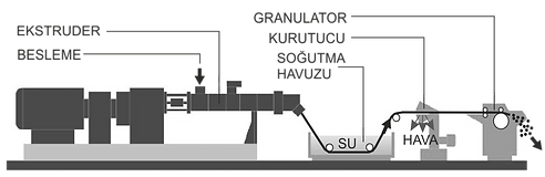

Pipe / Profile Production Lines
One method of classifying pipes is that they are made according to their source. Pipes: They are divided into two as Welded (Straight or Spiral) and Unwelded. Welded pipes are involved in metalworking. In other words, both welded and non-welded pipes can be produced from metals. However, pipes made of plastics are completely unwelded. The methods used in the production of welded pipes are special rolling and extrusion. After the typical extrusion process, the melt is passed through special pipe / profile gauges under pressure and the outline of the pipe form is determined.
This initial pipe profile is immediately taken to a vacuuming unit and entered into the target sizing process.
Here, basic properties such as wall thickness, inner diameter value, and tightness are shaped. The pipe is at the profile softening temperature, and after this unit is transferred to the cooling pool, the heat is transferred to the water. The advancement of the profile coming out of the extruder with pressure along the line is provided by the crawler tractor unit. The pipe of this unit, also defined as Caterpiller hammer, must be free-moving up and down in order to hold the profile with a pressure that will not crush it. This movement can be pneumatic, electric motor or manually controlled, which is not preferred. The working speed of the tractor unit should be completely synchronized with the extruder production speed. The pipe passing through this unit is also cut into slices after passing through an optional unit where inscriptions such as brand, production date, serial number, technical measurement values can be written on the profile with trace printing or ink if desired.

Wire Coating Production Lines
Wire coating is usually done using single screw extruders in which crosshead extrusion is carried out. The most fundamental element of the process is the mold on which the coating work is done. The basic process is carried out by wrapping and wrapping the wire, by applying the polymeric melt obtained by typical extrusion work on the wire that passes through the center of the mold with the same pressure and temperature. Generally, there is a 90 ° angle between the extruder and the line direction in wire coating production lines. The wire coating production process begins with solving the coiled wire spools to feed the line and passing the wire through the die center.
The wire is advanced to the pre-tension station to adjust the tension throughout the process. In order for the coating work to be healthy, the wire must be prepared and pre-heated for this. Hot over cross head mold station
The polymeric melt is passed through the coiled wire cooling basin. In order to prevent any weakening or growth in diameter in the coating of the wire, it is of great importance that the wire tension is stably and constantly the same. For this, synchronization of the extruder of the drawing unit and the wire unwinding reel is required. The wire passing through the cooling and drawing units is taken to the winding reels and wound until the required quantities are filled. Typical Polymers used in wire coating applications The polymers used in the cross head extrusion process in cable jacket applications vary. However, these polymers must have distinctive properties such as flexibility, electrical resistance, resistance to bad environmental conditions, and durability, which makes them ideal for this purpose. PE, PVC, PA, PBT, EVA, PP are polymers often used in wire coating work. Apart from these, thermoplastic elastomers, ethylene propylene copolymers

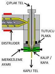
Hot Melt (Hot Melt)
Hot glue was developed in the 1940s as an alternative to water-based adhesives that were inadequate in humid climates. Today, in packaging and packaging, with many types such as single-sided, double-sided, masking,
It is frequently used in tape production addressing many application areas. Hot
In melt or hot glue core, applied as liquid in molten state but
It consists of thermoplastic polymers that solidify again as it cools. Cost effective,
easy to use, variety of formulas for application areas, storage
It has benefits and features in terms of ease, above all adhesion quality. Some of its very different types are:
Those with EVA:
It is suitable for both packaging and assembly formulas. It is economical and effective at standard hot melt temperatures between -20 and 180 ° C. EVA is the most common type of hot melt and is used in applications such as packaging and product assembly.
Those with PA:
It is used to formulate adhesives to create a better resistance to temperature extremes and chemicals from -80 to 270 ° C.
Those with polyamide:
Like EVA products, it is used only when higher heat resistance is needed.
Those with PP:
It is often used in spray formulations to create specific adhesive properties, such as a delayed setting time effective between -22 and 230 ° C.
Polyurethane (PUR) ones:
It is used for high chemical resistance.
PUR absorbs small amounts of moisture after it solidifies. Moisture absorption creates a permanent chemical change after a few days. This chemical change increases both the heat and chemical resistance of the adhesive. The chemical reaction allows PUR to form a structural bond similar to epoxies. PUR is perfect for a wide range of applications, but is widely preferred for woodworking.
Due to their temperature sensitive nature, hot melt adhesives are generally not suitable for use in high temperature environments or heat sensitive substrates. Common polymers used in the production of hot melt adhesives include polyurethane reactive, styrene-isoprene-styrene, and styrene-butadiene-styrene, although these polymers typically act as the carrier of the adhesive, not the adhesive itself.
Hot melt adhesives often require a dispensing tool or applicator, such as a glue gun or drum dispenser. Normally, waxes, plasticizers and other materials are added to the mix to improve certain properties such as flexibility and strength. BOPP film is generally preferred as carrier film in tape production. During the application, a Release Layer must also be created in order to open the spiral layers easily. This layer can be in the form of a solution or it can be waxed paper.
One of the main features that distinguish Hot Melt tapes from Acrylic ones is that they are at least three layers.
BOPP (Biaxially Oriented Polypropylene) Bi-Directional Polypropylene films are produced by stretching the PP film perpendicular to both machine and machine directions. In this way, improved hardness, high tensile strength, excellent optical properties and good water vapor barrier properties are obtained.
BOPP films range from 15 to 50 microns and are most commonly preferred between 15 and 30 microns. BOPP films can be monolayer or co-ex structures. In addition, acrylic and PVDC coating can be applied to further increase the film quality. These formed composite films mostly use homopolymer PP and random copolymer PP. Release lines, mostly cast film production line after BOPP production, are either direct second stage or third stage production lines after flexo printing. And the products that come out of here are semi-finished / semi-form products that will go for slicing, mostly for packaging and packaging bands.

The main component of the hot melt melt created for release is Aliphatic Hydrocarbon resin such as HIKOREZ A-1100, styrene and isoprene based, such as KRATON D-1161, an open, linear triblock copolymers with a polystyrene content of 15%. Characteristic feature. derived from gum resin derived glycerol esters such as MEGARA. Also, paraffinic process oils, coloring pigments are available. The release layer contains synthetic release polymers such as Tolien and RELEASE PP-100 at the head of solvent and carrier agents.
Adhesive tape family as above. Acrylic tapes do not bond as quickly as hot melt sealers. It has good initial tack, but a gradual tack build-up period of about one day is required to achieve maximum adhesion. However, it has better heat, UV and shear resistance. Therefore, these types of belts are recommended for longer term packaging.

